Timing regulator for outdoor gas apparatus

a technology for outdoor gas equipment and timing regulators, which is applied in the direction of functional valve types, operating means/releasing devices of valves, light and heating equipment, etc., can solve the problems of safety gas controllers that cannot shut off gas flow, safety gas controllers that can only stop gas flow, and gas flow may accidentally leak through gas flow indicators, etc., to achieve the effect of minimizing the manufacturing cost of timing regulators and enhancing the assembly operation of timing regulators

Active Publication Date: 2006-08-15
CAI AN
View PDF4 Cites 31 Cited by
  • Summary
  • Abstract
  • Description
  • Claims
  • Application Information

AI Technical Summary

Benefits of technology

[0013]Another object of the present invention is to provide a timing regulator, which comprises a safety gas controller for preventing the gas leakage from the gas source, wherein the safety gas controller is adapted to automatically return from a shut-off position back to the normal position. In other words, the timing regulator does not require a manual operation to release the shut-off position of the safety gas controller.
[0014]Another object of the present invention is to provide a timing regulator, wherein the safety gas controller comprises a thermal connector which is mounted to the gas outlet and is arranged to be deformed to shut off the gas flow through the gas channel over a safety temperature. In other words, in case of fire, the timing regulator can be automatically shut off to stop the gas flow from the gas source to prevent the gas leakage thereof.
[0015]Another object of the present invention is to provide a timing regulator, which comprises a timer device, wherein the upper platform, the lower platform, and the gear unit are securely attached to form a one piece integral unit such that no screw is needed to lock up the upper and lower platforms to retain the gear unit therebetween, so as to prevent the failure operation of the timer device and misalignment of the gear unit due to the loosened screw. In addition, the one piece integral timer device enhances the assembling operation of the timing regulator so as to minimize the manufacturing cost of the timing regulator incorporating with the timer device.
[0016]Another object of the present invention is to provide a timing regulator, wherein the timer device is mechanically engaged with the actuating arm to control the gas flow such that the timer device is securely held in position to prevent the failure operation of the timer device and the gas leakage therefrom.
[0017]Another object of the present invention is to provide a timing regulator, which comprises a rubber made gas tube, having a predetermined stretching ability, sealedly connected the gas discharging end of the timing regulator via the connecting device so as to prevent the gas leakage at the gas discharging end of the timing regulator in comparison with the conventional gas controller that the gas tube is directly connected to the gas discharging end of the gas controller.

Problems solved by technology

However, the safety gas controller has several drawbacks.
However, the gas flow indicator requires a small amount of the gas flow passing therethrough for measurement, such that the gas flow may accidentally leaked through the gas flow indicator.
In addition, the safety gas controller can only stop the gas flow through the pressure difference between the gas inlet and the gas outlet.
Therefore, the safety gas controller cannot shut off the gas flow due to the change of temperature such as fire accident.
In other words, such safety gas controller is unsafe to incorporate with any outdoor gas apparatus.
However, there is no mechanical engagement to substantially mount the timer gear assembly to the valve body to hold the timer gear assembly within the pressurized gas chamber in position such that the timer gear assembly may misalign with the actuating arm over a period of continuous use, which may cause the failure operation the timing device and the gas leakage of the valve body.
However, when the screw is loosen, especially over a period of continuous use, which fails to hold the upper and lower platforms in position, the gear unit cannot fittingly be engaged with each other.
In other words, the screw must be tight enough to lock up the gear unit between the upper and lower platforms, which may highly increase the manufacturing cost of the gas controller incorporating with the timing device.
In addition, the setting of the gear unit may accidentally be adjusted by detaching the upper platform from the lower platform which may cause the failure operation of the timer gear assembly.
Therefore, the timer gear assembly is disadvantage in practice use.

Method used


Image

  • Timing regulator for outdoor gas apparatus
  • Timing regulator for outdoor gas apparatus
  • Timing regulator for outdoor gas apparatus

Examples


Embodiment Construction

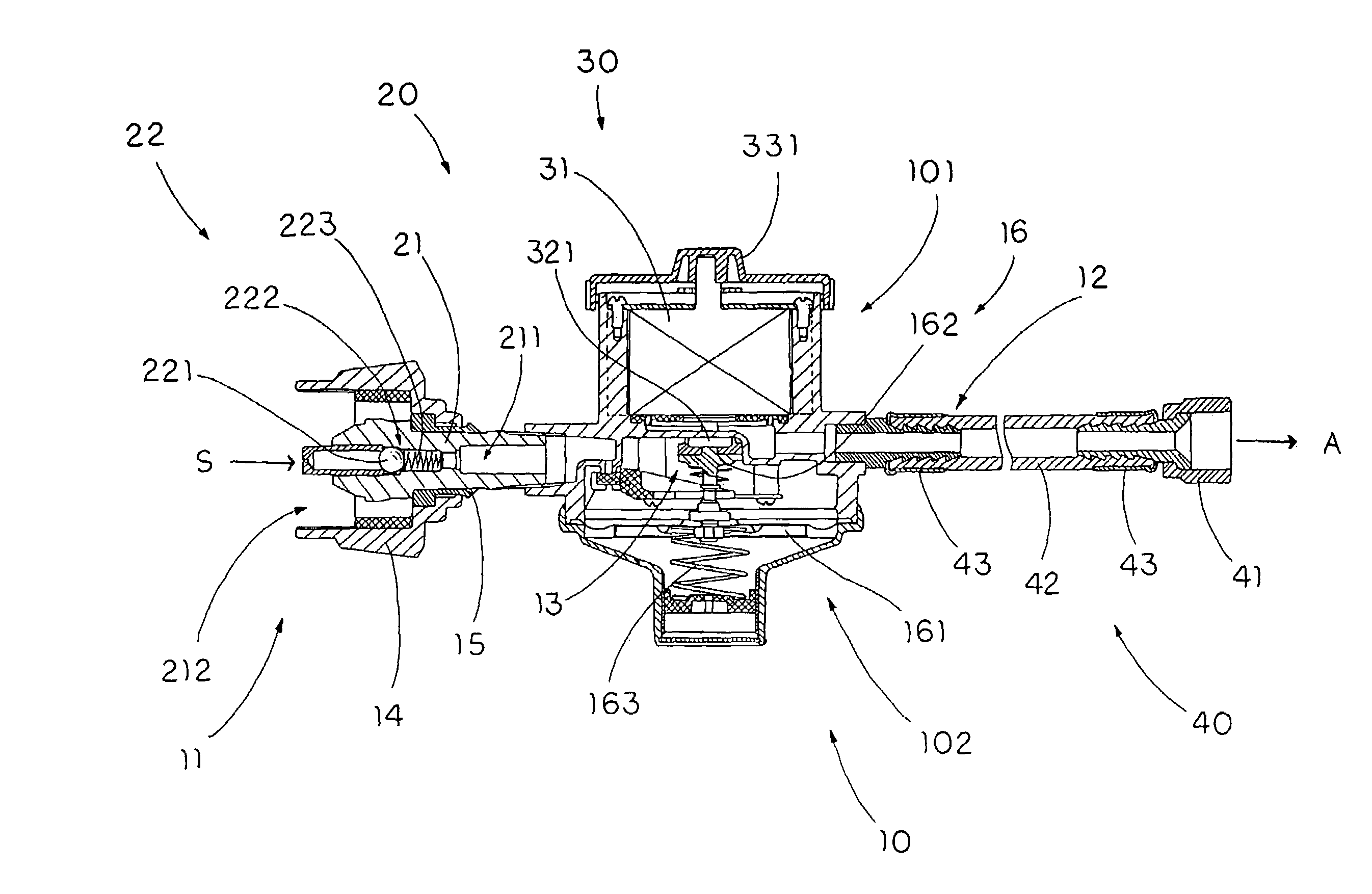
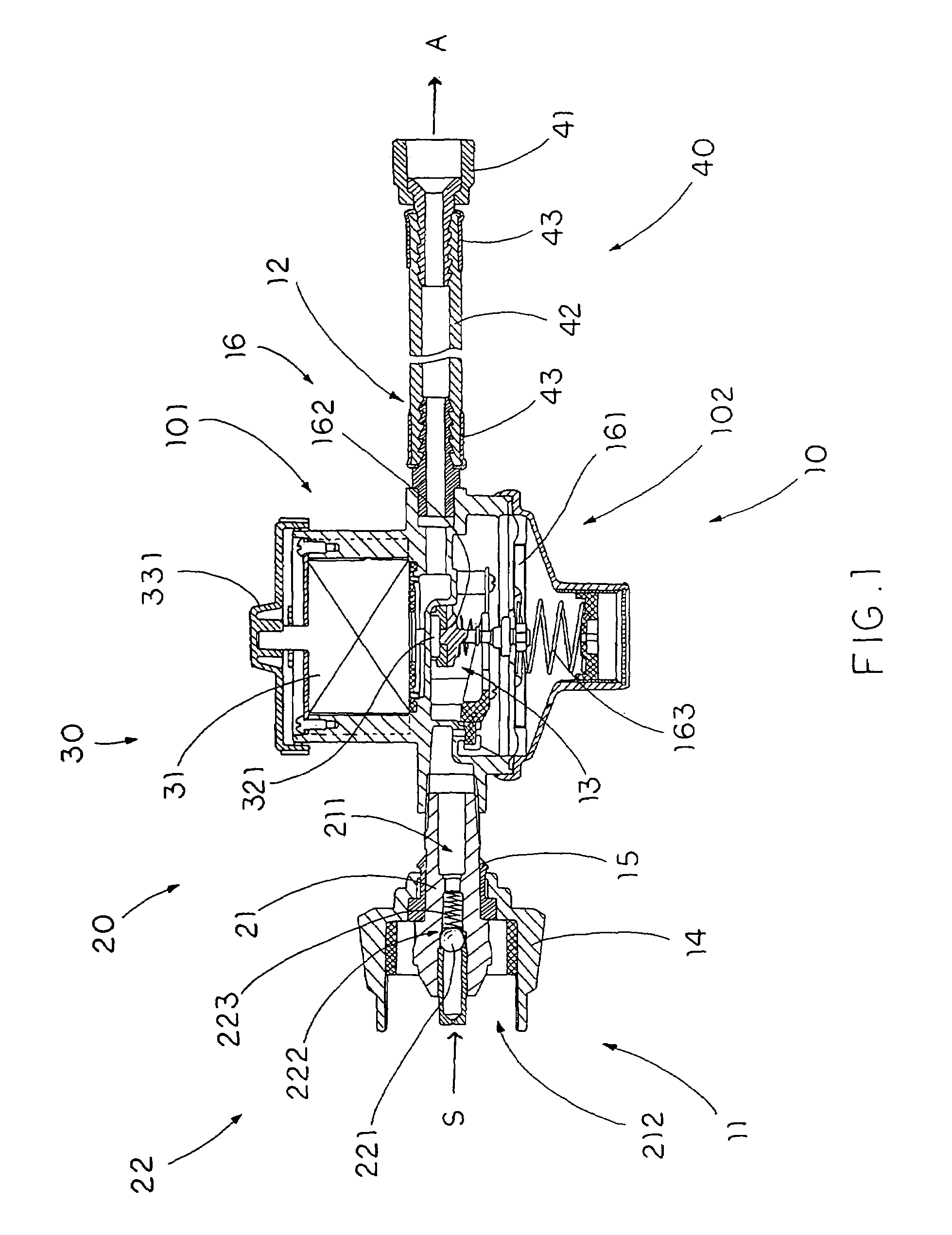
[0029]Referring to FIG. 1 of the drawings, a timing regulator according to the preferred embodiment of the present invention, wherein the timing regulator, which is arranged to operatively connect between a gas source S and an outdoor gas apparatus A to regulate a gas flow to pass from the gas source S to the outdoor gas apparatus A, comprises a valve body 10 and a gas controller 20.

[0030]The valve body 10 is constructed to obtain an operation temperature of the timing regulator from −40° C. to 55° C. for incorporating with the outdoor gas apparatus A. The valve body 10 has a gas inletting end 11, a gas discharging end 12 for connecting to the outdoor gas apparatus A, and a gas chamber 13 communicating between the gas inletting end 11 and the gas discharging end 12. The valve body 10 further comprises a safety gas connector 14 provided at the gas inletting end 11 for securely and sealedly connecting to the gas source S.

[0031]The gas controller 20 comprises a gas channel 21 having a ...


PUM


Abstract

A timing regulator, having an operation temperature of the timing regulator from −40° C. to 55° C., includes a valve body which has a gas discharging end for connecting to an outdoor gas apparatus and a safety gas connector provided at a gas inletting end for securely connecting to a gas source, a gas controller including a safety device for blocking the gas flow passing through the valve body when a gas pressure at the gas discharging end of the valve body is higher than a safety gas pressure at the gas inletting end thereof, and a timer device disposed in the valve body for selectively regulating the gas flow via a preset time frame.

Description

BACKGROUND OF THE PRESENT INVENTION[0001]1. Field of Invention[0002]The present invention relates to a gas controller, and more particularly to a timing regulator especially for an outdoor gas apparatus, such as a gas barbecue grill, wherein the timing regulator has a rigid and durable structure that allows to be operated within an operation temperature from −40° C. to 55° C.[0003]2. Description of Related Arts[0004]A safety gas controller is generally incorporated with a gas apparatus to prevent gas leakage from a gas source. U.S. Pat. No. 4,579,142, generally suggests a safety gas controller comprising a flow channel having a gas outlet and a gas inlet connected to the gas source, and a safety valve disposed in the gas channel to control a flow of gas to pass through the flow channel from the gas inlet to the gas outlet. The safety valve comprises a ball member rotatably disposed within the flow channel in such a manner that when the gas flow is greater than a safety flow, the gas...

Claims


Application Information

Patent Timeline
Patent Type & Authority Patents(United States)
IPC IPC(8): F16K31/48F23N5/22F23N5/24
CPCF16K31/485F23N5/247F23N5/22Y10T137/7727Y10T137/86389
Inventor CAI, AN
Owner CAI AN
Why Eureka
Try Eureka