Boat lift brake apparatus

a brake apparatus and boat lift technology, applied in waterborne vessels, hoisting equipment, elevators, etc., can solve the problems of significant power away from the drive motor, inefficient energy consumption, and almost impossible to control the descent. achieve the effect of reducing energy consumption

Inactive Publication Date: 2006-08-15
QUALITY BOAT ELEVATORS
View PDF8 Cites 2 Cited by
  • Summary
  • Abstract
  • Description
  • Claims
  • Application Information

AI Technical Summary

Benefits of technology

[0005]It is therefore an object of this invention to provide a boat lift braking system, which does not require that braking be performed by the lift motor and which therefore operates more efficiently than existing brake systems.

Problems solved by technology

Moreover, a controlled descent would be almost impossible to achieve.
This is very energy inefficient.
This draws significant power away from the drive motor.
As a result, an excessively large capacity motor may be required.

Method used


Image

  • Boat lift brake apparatus
  • Boat lift brake apparatus
  • Boat lift brake apparatus

Examples


Embodiment Construction

[0017]Other objects, features and advantages will occur from the following description of preferred embodiments and the accompanying drawings, in which:

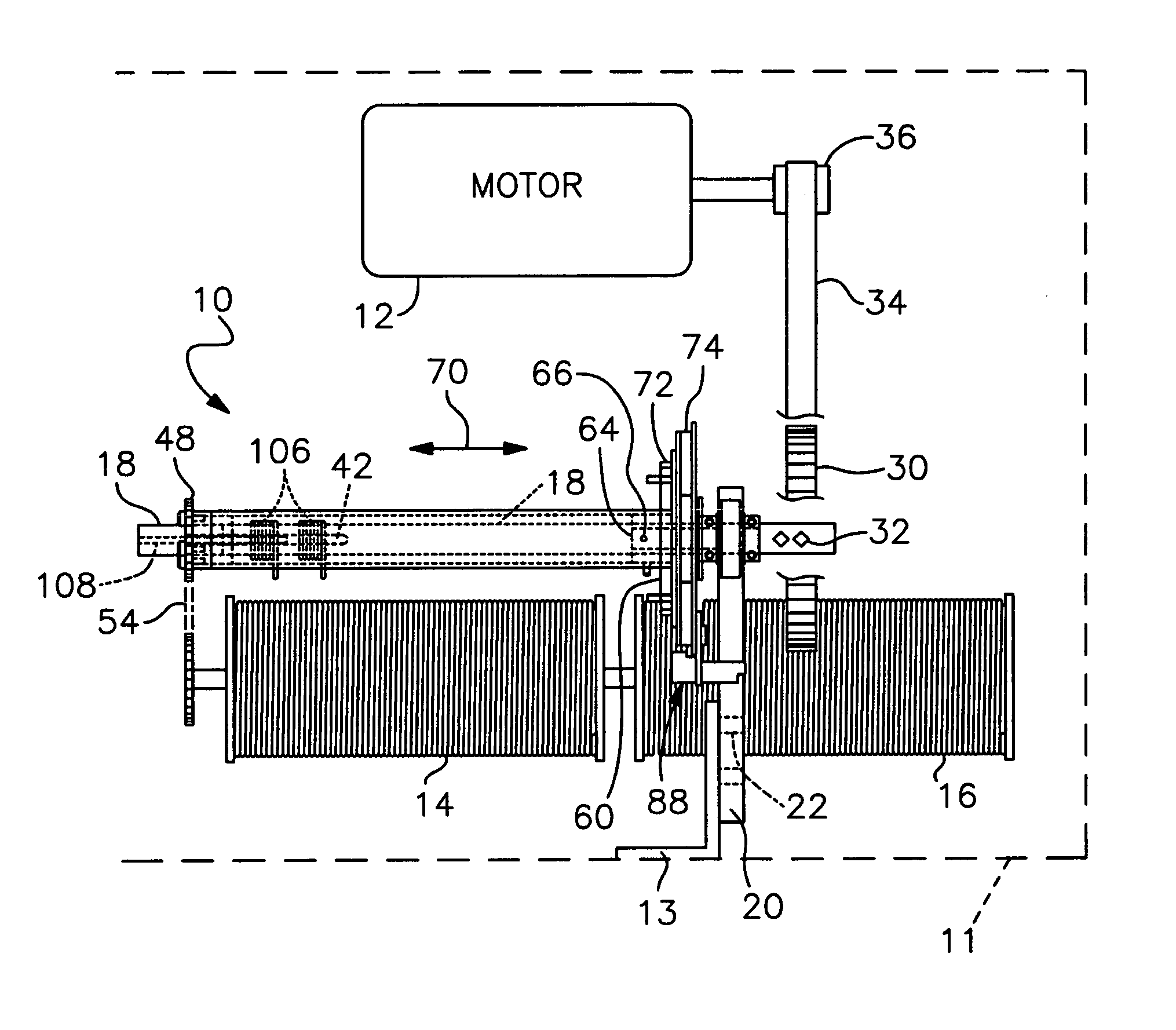
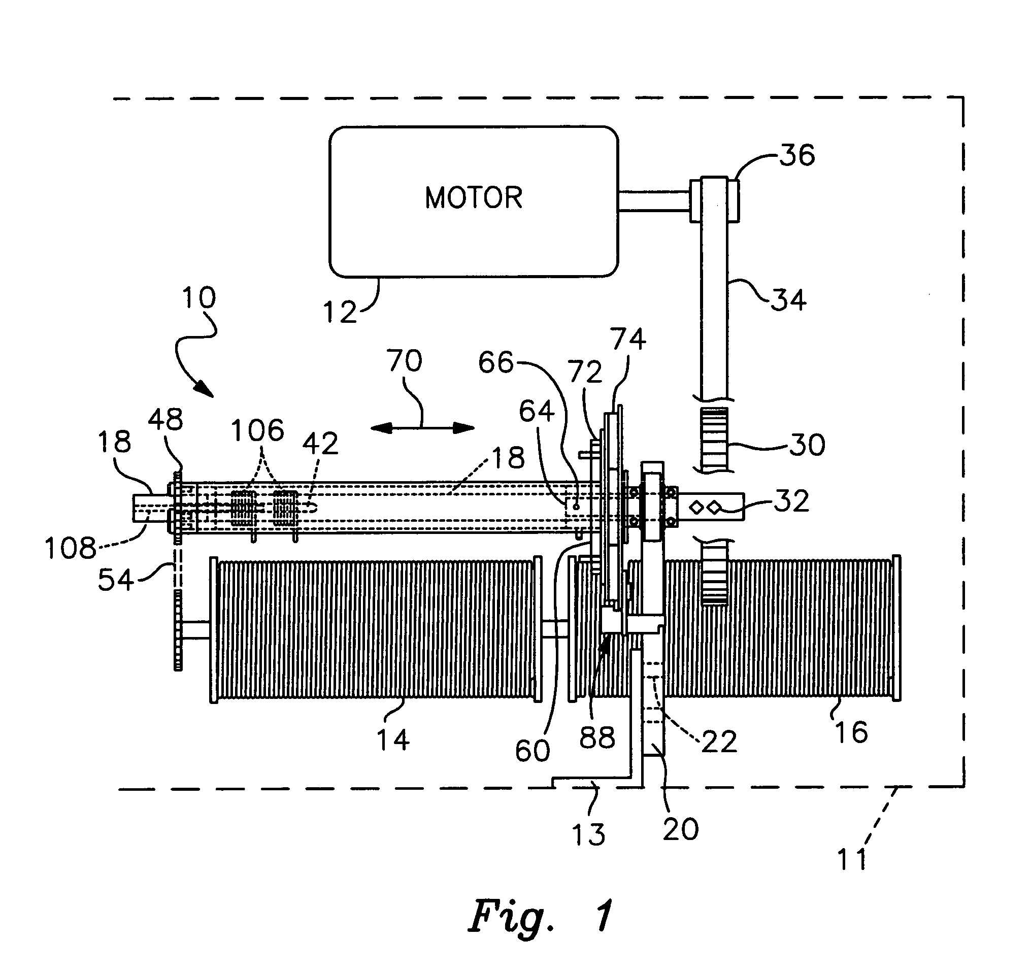
[0018]FIG. 1 is an elevational, partly schematic view of the brake apparatus of this invention operably mounted in the drive housing of a boat lift;

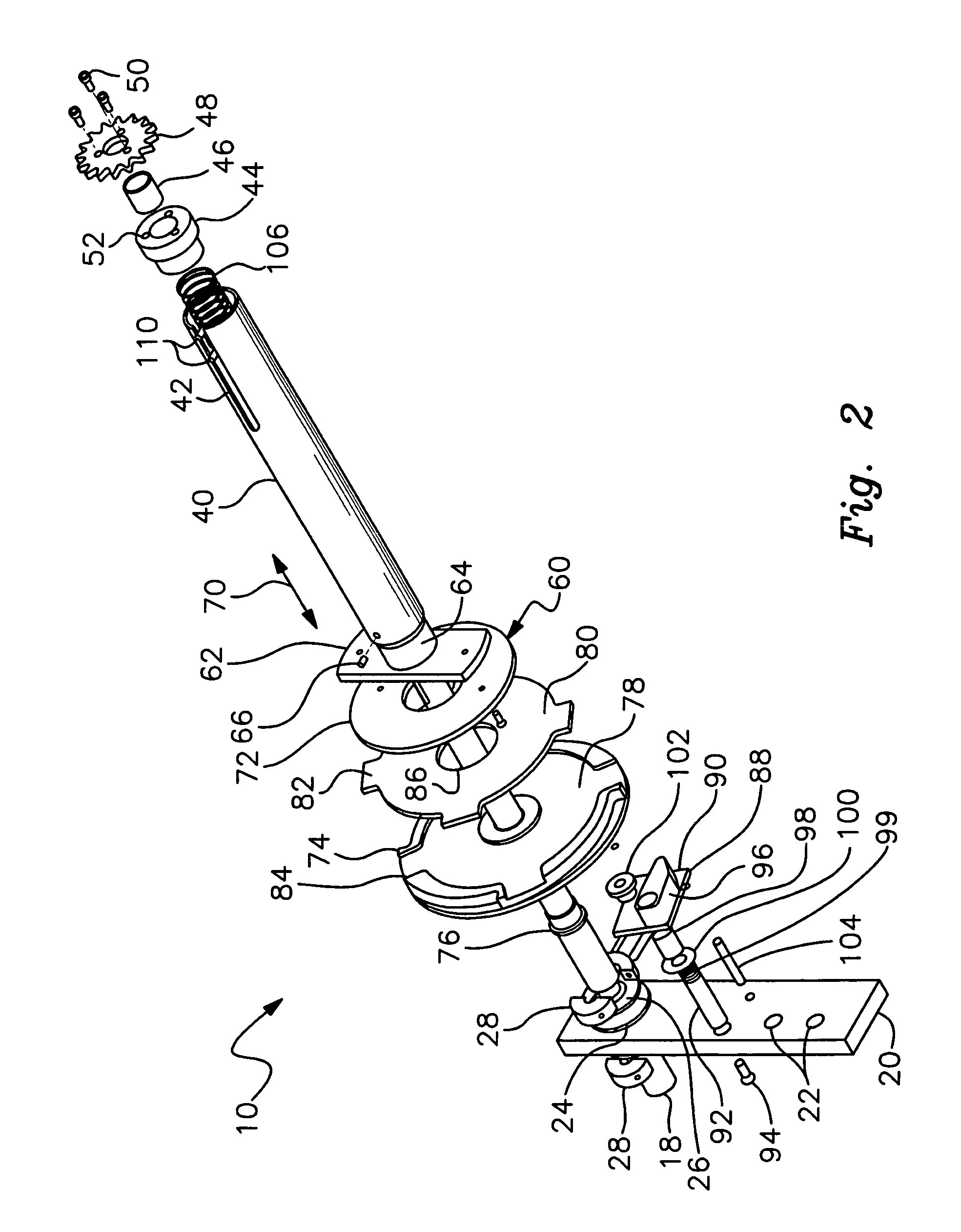
[0019]FIG. 2 is an exploded view of the boat lift braking system;

[0020]FIG. 3 is an upper perspective view of the braking system in an assembled condition;

[0021]FIG. 4 is a lower perspective view of the assembled braking system specifically depicting a side of the torsion tube opposite the side shown in FIG. 3;

[0022]FIG. 5 is a cross sectional view taken along line 5—5 of FIG. 3;

[0023]FIG. 6 is a top view of the braking system; and

[0024]FIG. 7 is an elevational view of the mounting collar by which the drive shaft of the brake is mounted to a support element of the boat lift.

[0025]There is shown in FIGS. 1–5 a boat lift braking system 10. The braking system is particularly suitable for con...


PUM


Abstract

A boat lift braking system includes a threaded shaft driven by the boat lift motor. A torsion tube disposed about the shaft carries an interiorly threaded nut that interengages the peripheral threads of the shaft. A rotor is mounted to the nut adjacent a brake pad that is supported by a ratchet component. A pawl mechanism cooperates with the ratchet component for limiting rotation of the ratchet component in a first direction and permitting rotation of the ratchet component about the shaft in a second direction. The torsion tube is connected through a reduction apparatus to the winder of the boat lift. When the lift is at rest, a torsion spring drives the torsion tube and rotor against the brake pad and the ratchet component interlocks with the pawl mechanism to hold the lift at a desired elevation. When the motor is driven to lower the lift, the shaft is driven within the torsion tube such that the rotor momentarily disengages the pad. Immediately thereafter, the torsion spring forces the rotor back against the pad and these counteracting forces continuously repeat to provide a controlled descent. When the motor is operated to raise the lift, the shaft is driven relative to the torsion tube such that the rotor and pad interlock. The ratchet component disengages the pawl and the torsion tube turns so that the lift can be elevated.

Description

RELATED APPLICATION[0001]This application claims the benefit of U.S. Provisional Application Ser. No. 60 / 456,343, filed Mar. 20, 2003.FIELD OF THE INVENTION[0002]This invention relates to a brake apparatus and, more particularly, to a brake specifically designed for use in a boat lift.BACKGROUND OF THE INVENTION[0003]Boat lifts require the use of an appropriate braking system in order to hold the raised or hoisted marine vessel in an elevated condition. The braking system also permits the boat lift operator to lower the vessel in a controlled manner. Without an appropriate brake, the boat would freefall whenever the lift motor is deactivated. Moreover, a controlled descent would be almost impossible to achieve.[0004]Presently, the gear box provides the required braking for most boat lifts. More particularly, braking is typically accomplished through the worm gear of the drive motor, which both supports the load at rest and allows the load to descend in a controlled fashion. This is ...

Claims


Application Information

Patent Timeline
Patent Type & Authority Patents(United States)
IPC IPC(8): B66B1/32
CPCB66D5/32B66D5/12
Inventor MCLAUGHLIN, SHAWN M.YLIPELKONEN, RIKU
Owner QUALITY BOAT ELEVATORS
Why Eureka
Try Eureka