Unloading system for particulate material

a technology of unloading system and particulate material, which is applied in the direction of refuse transferring, transportation items, applications, etc., can solve the problems of not being able to manoeuvre a semi-trailer or highway tractor truck into position relative to a conventional unloading system, and not being able to achieve full-time employment. the opportunity for continuous decreas

Inactive Publication Date: 2006-08-15
BOURGAULT INDS
View PDF49 Cites 62 Cited by
  • Summary
  • Abstract
  • Description
  • Claims
  • Application Information

AI Technical Summary

Benefits of technology

[0059]A hitch is mounted on the end of the platform opposite the main conveyor. The hitch is hinged to the platform and linked to the platform transport wheel mechanism. As the platform transport wheels are actuated to raise or lower the conveyor end of the platform, the hitch moves to raise or lower the hitch end of the platform. The hitch thus supports the platform for transport, and is allowed to pivot on its hinge to lower the platform to the ground for operation of the unloading system, without having to uncouple the towing vehicle from the unloading system. A manually operated hitch jack is provided for supporting the hitch end of the system when a towing vehicle is not connected.
[0060]A system may also be provided for assisting a truck driver in properly positioning a truck / trailer outlet over the unloading system. This feature may consist of a retractable cord or tape that can be marked to correspond to the driver's position when each truck / trailer outlet is properly positioned. Once the system is calibrated, a driver need only stop the truck when the driver's position corresponds to a mark on the cord / tape and the respective outlet will be properly positioned over the unloading system.

Problems solved by technology

As large grain auger / conveyors have come into use, it is no longer possible or easy to practically position them by hand, and some are sufficiently large to require a tractor to tow, position and power them.
It is much more difficult or at times impossible to manoeuvre a semi-trailer or highway tractor trucks into position relative to a conventional unloading system.
Work on a grain farm is seasonal in nature, and opportunities for full time employment have continuously decreased over time.
Whereas in the past another person may have been available to assist with positioning equipment, that is no longer the case in many situations.
To compound the problem, the age of the farming population has increased significantly and farmer operators are less able to perform physically demanding tasks.
Safety is also an issue when an operator is working alone, as farmers are often required to do.
This is a somewhat cumbersome system that requires the swingable auger to be swung under the grain trailer and removed each time the trailer is unloaded.
This arrangement is often not convenient or even suitable for some yards where the ability to manoeuvre the highway tractor unit and the grain semi-trailer is restricted by the grain bins themselves, buildings, overhead power lines or trees, et cetera.
This type of system requires cumbersome manual handling of the swing-away auger extension before and after unloading, and for each trailer and often for each unloading chute in a semi-trailer train.
This approach still has serious drawbacks in that such a ramp is typically too large to be handled manually Y and requires another tractor to carry and position it.
The positioning of auger and its power unit remain somewhat awkward and less than ideal.
However, this device uses an endless belt rather than screw lateral transfer augers and has a ramp detachable from the transfer conveyor.
The components are too large to be handled manually so another tractor is required to carry and position the components.
Other devices use an expensive, separately powered intermediate transfer system.
One disadvantage of this invention is that the horizontal transfer conveyor must be towed and positioned separately from the elevating conveyor that it is intended to discharge into.
A further disadvantage is the need to manually elevate the hitch for attachment to the towing vehicle, and where necessary, to install and remove the transport wheels.
Yet another disadvantage is the need to manually fold the ramps for transport.
This equipment as developed to date, is typically cumbersome, complex and costly and leaves unaddressed, opportunities to further increase cost effectiveness.
Each piece of the unloading equipment system must still be separately positioned when moving from one bin to another, consuming valuable time.
Complexity leads to more required maintenance, a higher probability of breakdown and increased costs.
High cost compounds the economic pressures on farming operations.
One of the problems with this system is that it is limited to a belt-type conveyor, to be able to drive upon it without damaging it.
Another problem is the relatively narrow opening to receive material because the width of the belt is limited to that which can be used in the elevating section.
Also, the structure / mechanism needed to support and operate a drive-over belt may be relatively tall which limits the clearance between the belly dump chute of a grain trailer and the flexible hopper above the device and also the size of the opening into which material can be dumped.
It is not likely to be economical to build the unit heavy enough to withstand such loading.
This patent does not address the difficulties in an agricultural situation where bulk particulate materials must be unloaded onto the conveyor from large, difficult to manoeuvre, multi-trailer, highway tractor truck units.

Method used


Image

  • Unloading system for particulate material
  • Unloading system for particulate material
  • Unloading system for particulate material

Examples


Embodiment Construction

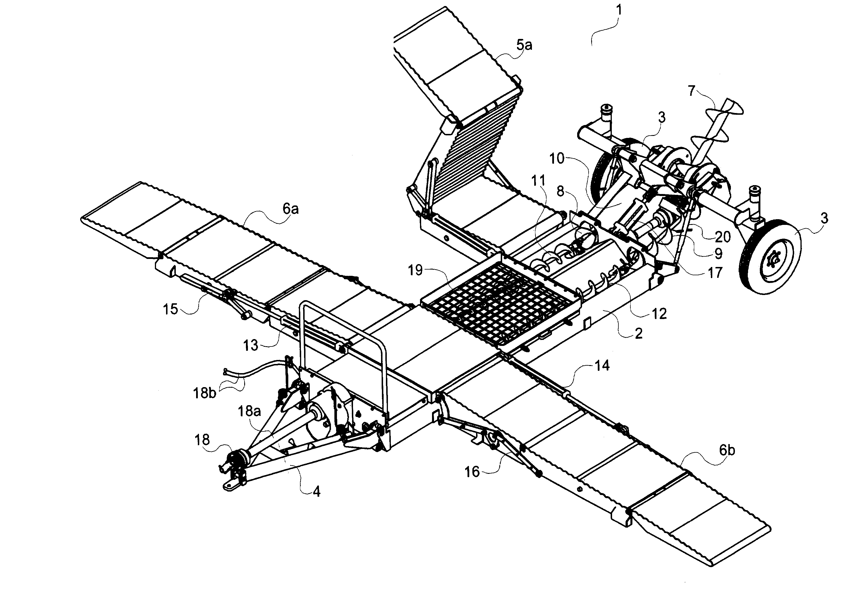
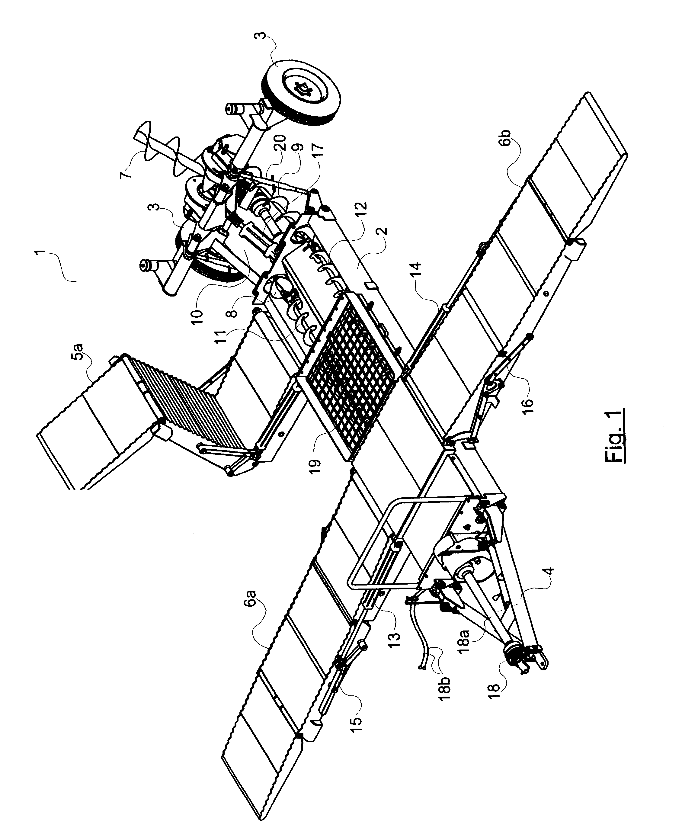
[0073]FIG. 1 gives an overall perspective view with some portions cut away or removed of the present invention shown generally as 1. The unloading device for particulate material, and more specifically for unloading grain from trucks and moving it into bins, has a generally longitudinal platform 2 which is supported at the rear end by retractable transport wheels 3 and at the front end by a hingedly connected hitch 4. The invention has a pair of right and left ramps at the rear and at the front. The centre portions of each of the front and rear ramps are integrally connected and form a portion of said platform.

[0074]In FIG. 1, the rear right ramp which is foldable is marked as 5a, while 5b has been removed for clarity of illustration. The front pair of ramps are marked as 6a and 6b. The ramps are parallel to one and other and spaced apart to allow a large grain truck, in fact, even an 18-wheeler, to drive up and then down the opposite side while unloading of material through cargo d...


PUM


Abstract

This invention concerns a new grain unloading system using an integrated ramp, horizontal transfer conveyor and elevating system. The unit is towed, positioned and powered by an agricultural tractor.

Description

PRIORITY CLAIM[0001]Priority is claimed based on Canadian Patent Application No. 2,393,119, filed Jul. 12, 2002.FIELD OF THE INVENTION[0002]This invention is in the field of particulate material unloading systems, and particularly addresses improvements in efficiency and ease of use of systems for unloading granular agricultural materials from transport vehicles into storage bins, or other generally larger transport vehicles.BACKGROUND[0003]In farming, “grain augers” are commonly used to unload granular agricultural materials from trucks into bins.[0004]Over the years, the scale of farms and of the equipment used in farming has progressively increased. Formerly, loading / unloading augers were relatively small and light, and it was possible for a physically fit operator to manually position them for use (operation). It was also possible for a reasonably skilled operator to back up a simple dump truck and position its discharge chute over the inlet of a material transfer auger. Also in...

Claims


Application Information

Patent Timeline
Patent Type & Authority Patents(United States)
IPC IPC(8): B65G41/00B65G67/24
CPCB65G67/24B65G47/18
Inventor KIRSCH, JASON R.
Owner BOURGAULT INDS
Why Eureka
Try Eureka