Supercharge Your Innovation With Domain-Expert AI Agents!

Apparatus and method of winding optical fiber sensor coil for fiber optic gyroscope

a fiber optic gyroscope and optical fiber sensor technology, applied in the direction of optical elements, turn-sensitive devices, instruments, etc., can solve the problem that the other half of the optical fiber cannot be unwounded from the spool, and achieve the effect of quick and efficien

Inactive Publication Date: 2006-08-15
KOREA ADVANCED INST OF SCI & TECH
View PDF7 Cites 2 Cited by
  • Summary
  • Abstract
  • Description
  • Claims
  • Application Information

AI Technical Summary

Benefits of technology

This method allows for quick and efficient quadrupole winding of optical fibers, reducing the time required for winding long fibers and enabling mass production of optical fiber sensor coils with consistent tensile force and minimized risk of fiber snapping.

Problems solved by technology

In the case of winding an optical fiber while rotating a spool on which the optical fiber is to be wound, a problem is caused in that, when one half of the optical fiber, which is wound on one reel, is wound on the spool, the other half of the optical fiber cannot but be unwounded from the spool.

Method used


Image

  • Apparatus and method of winding optical fiber sensor coil for fiber optic gyroscope
  • Apparatus and method of winding optical fiber sensor coil for fiber optic gyroscope
  • Apparatus and method of winding optical fiber sensor coil for fiber optic gyroscope

Examples


Embodiment Construction

[0013]Reference will now be made in greater detail to a preferred embodiment of the invention, an example of which is illustrated in the accompanying drawings. Wherever possible, the same reference numerals will be used throughout the drawings and the description to refer to the same or like parts.

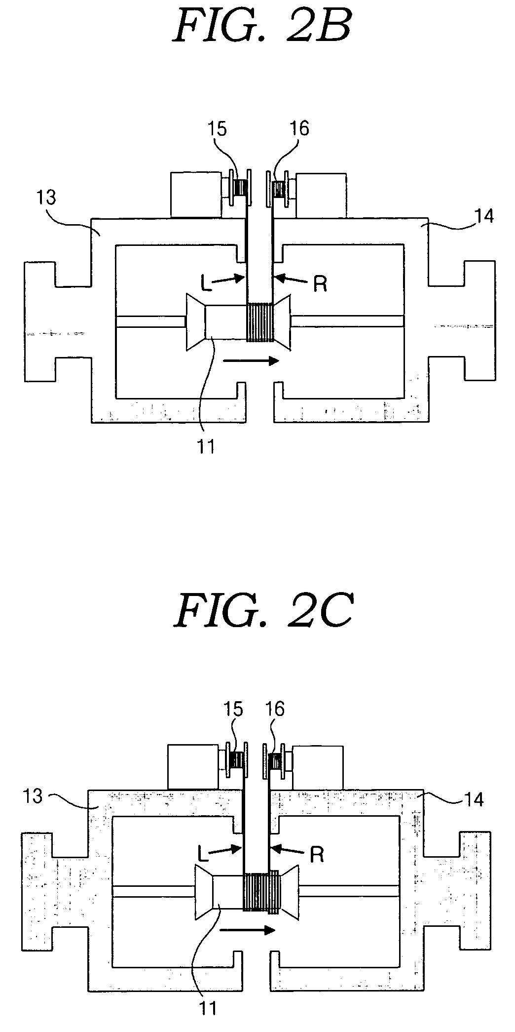
[0014]FIG. 1 is a perspective view illustrating an apparatus for winding an optical fiber in the form of a quadrupole in accordance with an embodiment of the present invention. The winding apparatus includes a spool 11, which is fitted around a center shaft 10. To allow an optical fiber to be wound thereon, the spool 11 has substantially a cylindrical configuration. Also, in order to delimit a winding range of the optical fiber, a pair of inclined projections are formed at both ends of the spool 11, respectively. Both ends of the center shaft 10 are supported by a pair of support sections 12, respectively. In this preferred embodiment of the present invention, the center shaft 10 and the s...


PUM

PropertyMeasurementUnit
rotationaaaaaaaaaa
lengthaaaaaaaaaa
timeaaaaaaaaaa

Abstract

An apparatus for winding, in the form of a quadrupole, an optical fiber used for forming a sensor coil of a fiber optic gyroscope. A center shaft is supported by a pair of support sections. A cylindrical spool is fitted around the center shaft. A pair of winding disks are arranged adjacent to both ends of the spool so that they can be rotated about the center shaft. A pair of reels are mounted to facing surfaces of the winding disks so that both halves of the optical fiber to be wound on the spool can be wound on the reels, respectively. The winding disks can be rotated at the same velocity in opposite directions. The cylindrical spool is installed to be reciprocated along an axis of the center shaft. The respective reels mounted to the winding disks are spaced apart from each other by a predetermined interval.

Description

PRIORITY CLAIM[0001]This application claims priority from Korean Patent Application No. 10-2002-0078272 filed 10 Dec. 2002, which is herein incorporated by reference.FIELD OF THE INVENTION[0002]The present invention relates to an apparatus and a method for winding an optical fiber in the form of a quadrupole, which can be adapted to the manufacture of an optical fiber coil used for a fiber optic gyroscope.DESCRIPTION OF THE PRIOR ART[0003]An optical fiber sensor coil used in a fiber optic gyroscope should be wound in the form of a quadrupole so as to decrease an error rate caused by changes in surrounding environment. In order to form the quadrupole, winding the optical fiber should be started from a middle portion of the optical fiber.[0004]A conventional method for winding an optical fiber will be described hereafter. First, in a state wherein a length of the optical fiber is divided into halves, both halves of the optical fiber are respectively wound on different reels. Then, rel...

Claims


Application Information

Patent Timeline
Patent Type & Authority Patents(United States)
IPC IPC(8): B21C47/14H01F41/06G01C19/00G02B6/00G01C19/58G01C19/72
CPCG01C19/722G01C19/72
Inventor KIM, CHUN GONYOON, HYUK JINKANG, SANG GUKLEE, WON JUN
Owner KOREA ADVANCED INST OF SCI & TECH
Features
  • R&D
  • Intellectual Property
  • Life Sciences
  • Materials
  • Tech Scout
  • Unparalleled Data Quality
  • Higher Quality Content
  • 60% Fewer Hallucinations
Learn More