Switch for portable light

a portable light and switch technology, applied in mechanical equipment, wound springs, lighting and heating apparatus, etc., can solve the problems of affecting the operation of the switch, so as to achieve the effect of convenient fabrication, low cost, and high reliability

Inactive Publication Date: 2006-08-15
ARTHUR JAMES DAVID
View PDF5 Cites 11 Cited by
  • Summary
  • Abstract
  • Description
  • Claims
  • Application Information

AI Technical Summary

Benefits of technology

[0006]The preferred embodiment teaches how a spring—such as a helical spring fashioned of steel, stainless steel, copper alloy, brass, or other suitable metal or alloy, with or without chromium or other protective plating—can be combined with a suitable array of contacts to produce a multi-position shorting switch that is inexpensive, durable, and reliable. Said switch can be readily fabricated on one side of a printed circuit board, allowing it to operate circuitry assembled on the opposite side of same. Furthermore, said switch can be contained within the protective environment of the flashlight housing, facilitating construction of waterproof flashlights.
[0007]Additionally, the instant invention provides for contacting an electrode of a dry cell, thus combining an additional function without additional cost, reducing parts count, and reducing the number of interconnection points in the flashlight's electrical circuit. Reliability is accordingly increased.

Problems solved by technology

All of these switches require penetration of the flashlight body, leaving gaps and openings through which water can enter and ruin the flashlight.
Slide switches in particular are vulnerable to leakage.
Further, while rubber domes with round rubber gasket skirts have been developed to cover pushbutton switches, providing some measure of water resistance, the result falls short of full water-tightness.
Said switch, while effective in a conventional incandescent flashlight, does not provide means for controlling a multiplicity of modes for a more flexible, more capable electronic flashlight.

Method used


Image

  • Switch for portable light
  • Switch for portable light
  • Switch for portable light

Examples


Embodiment Construction

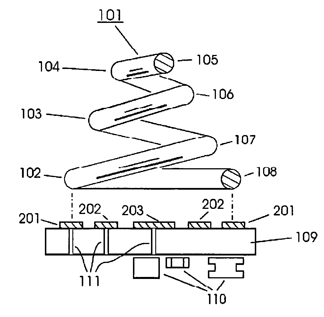
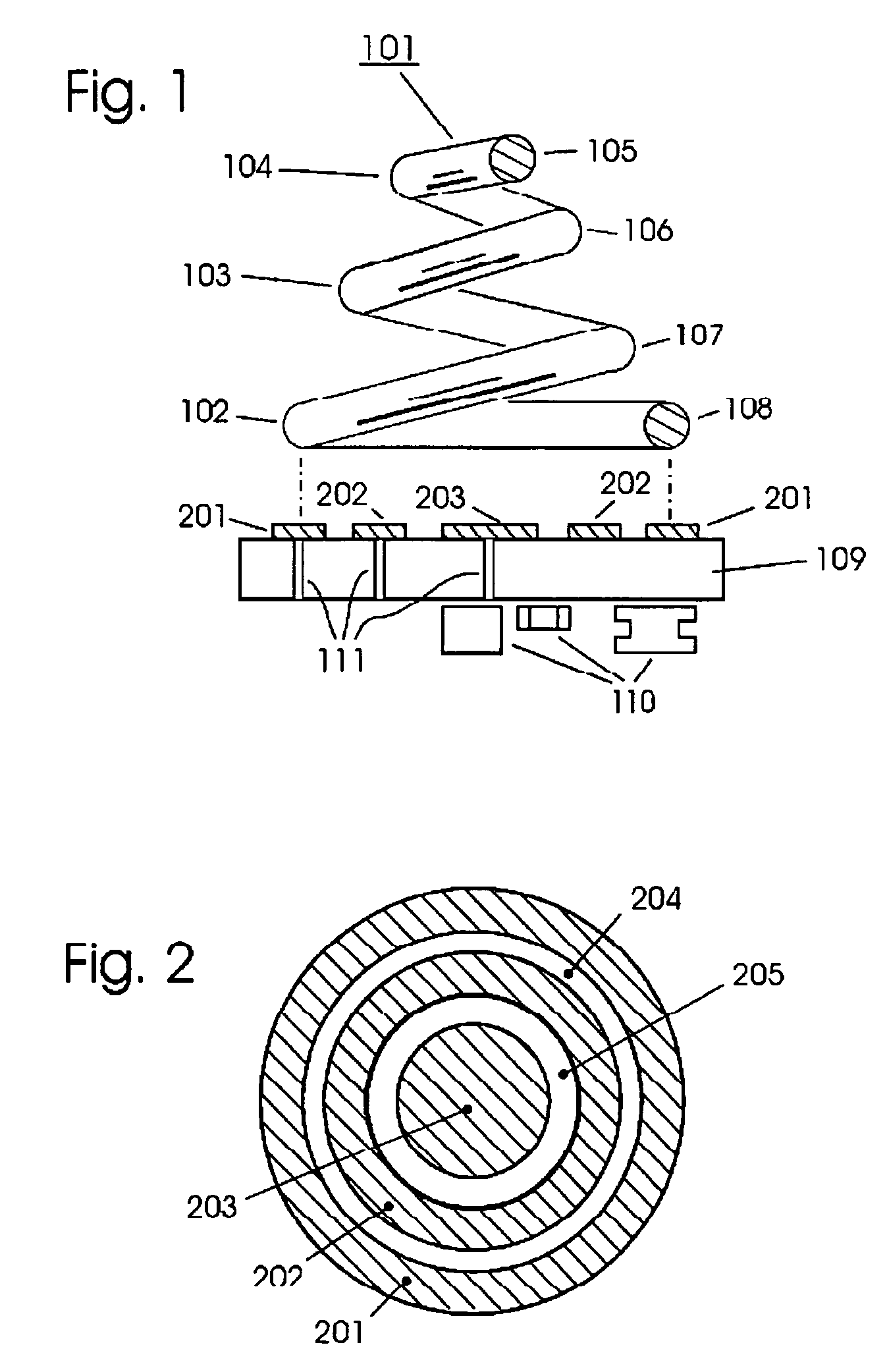
[0011]FIG. 1 depicts one preferred embodiment of the invention. A helical spring 101 made of a suitable electrically conductive material such as (but not limited to) steel, stainless steel, copper alloy, brass, or other suitable metal or alloy, with or without chromium or other protective plating, possessing coils 102–108, is positioned over concentric annular contacts 201–203. Said contacts 201–203 may be conductors laminated to a printed circuit board. 109. Connections 111 connect contacts 201–203 to circuitry 110.

[0012]FIG. 2 is a top-view of contacts 201–203, showing said contacts as well as insulating gaps 204–205. Gaps 204–205 serve to electrically isolate contacts 201–203 from each other until such time as the invention is activated. Contacts 201–203 may be supported by an insulating substrate, such as a fiberglass printed circuit board. Depiction of connections from contacts 201–203 to external circuitry has been omitted for clarity, but should be obvious to those skilled in...


PUM


Abstract

An electrical switch comprising a helical spring, progressively compressed onto concentric annular contacts, provides a mechanism for operating a portable light or other devices, and for engaging multiple modes of operation of said device(s), for example a portable electronic flashlight.

Description

FIELD OF THE INVENTION[0001]This invention relates to electrical switches, and more particularly to switches controlling the operation of electronic flashlights.DESCRIPTION OF THE RELATED ART[0002]Contemporary small, portable lights or flashlights most commonly use one spring and one fixed contact for connections to the cathode and anode of a dry cell battery, respectively. The spring in these units commonly presses into and connects with the cathode of the dry cell battery, and said spring's spring force is used to press the dry cell battery's anode into a second, fixed contact, inferior to the bulb assembly. Metallic straps or wires are used to connect these contacts sequentially to the flashlight's bulb and power switch, respectively providing means for conveying electrical power to the flashlight's bulb, and for interrupting that power to turn the light on and off. In the case of flashlights with metallic bodies the body itself may serve as part of the circuit, replacing one of ...

Claims


Application Information

Patent Timeline
Patent Type & Authority Patents(United States)
IPC IPC(8): F21V23/04F16F1/08F21L4/00F21L4/04H01H1/24
CPCF16F1/08H01H1/242F21V23/0414F21L4/005
Inventor ARTHUR, JAMES DAVID
Owner ARTHUR JAMES DAVID
Why Eureka
Try Eureka