Chemical mechanical polishing apparatus and methods using a polishing surface with non-uniform rigidity

a technology of mechanical polishing and non-uniform rigidity, applied in the direction of flexible wheel, manufacturing tools, lapping machines, etc., can solve the problems of non-uniform surface, unacceptably non-uniform polishing, wear of clamp pads, etc., and achieve less rigidity, less rigidity, less rigidity

Inactive Publication Date: 2006-08-15
SAMSUNG ELECTRONICS CO LTD
View PDF11 Cites 4 Cited by
  • Summary
  • Abstract
  • Description
  • Claims
  • Application Information

AI Technical Summary

Benefits of technology

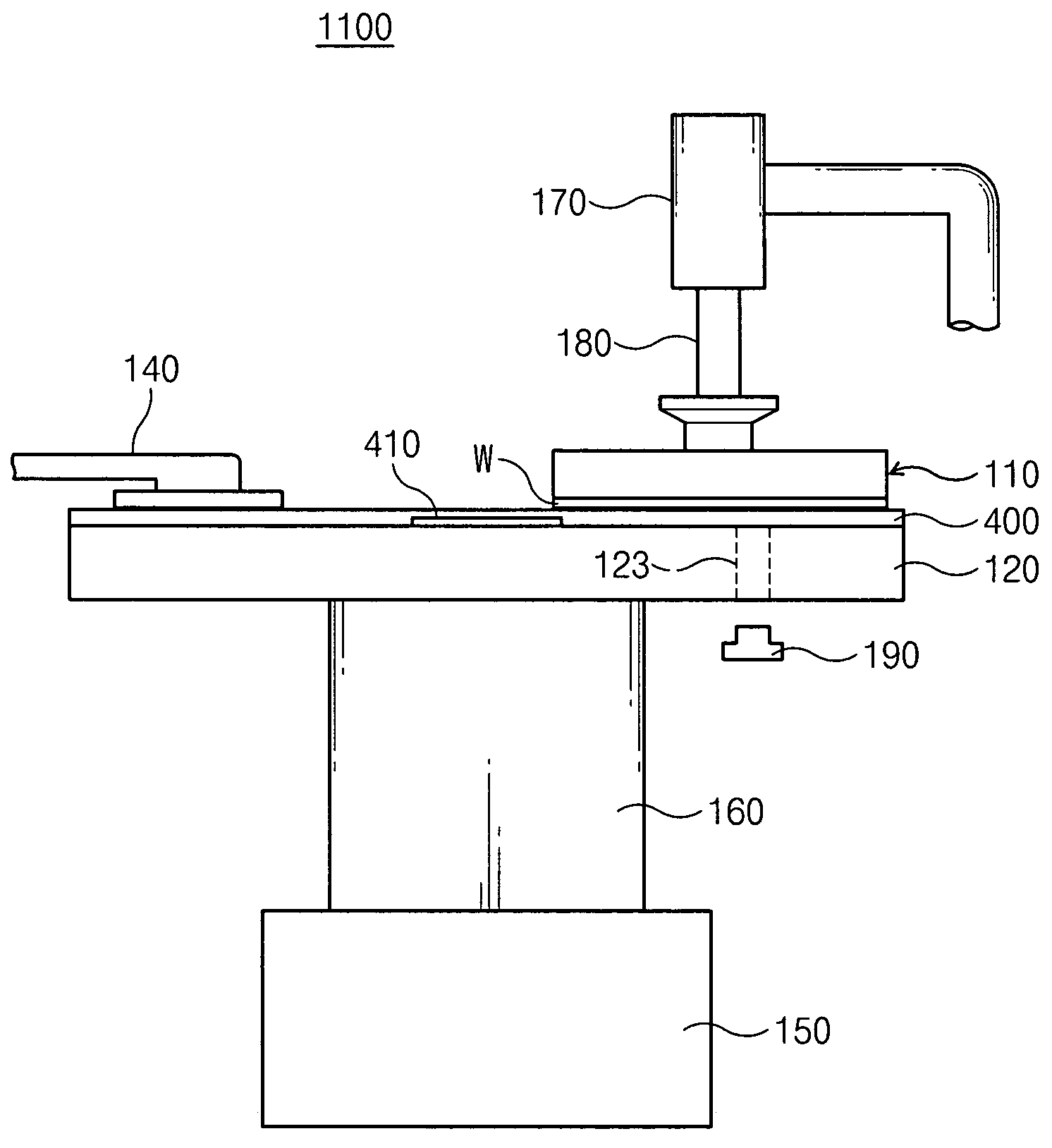
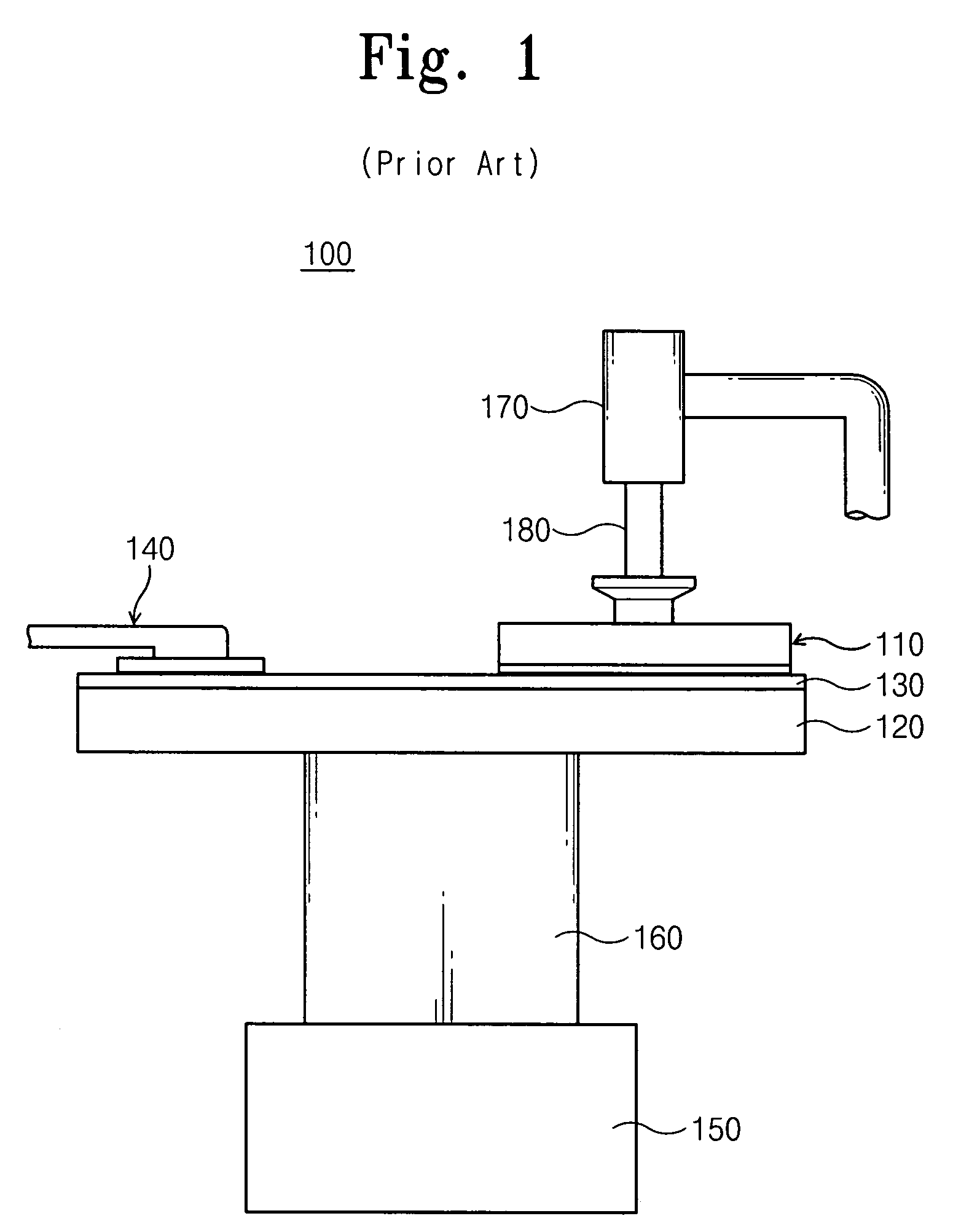
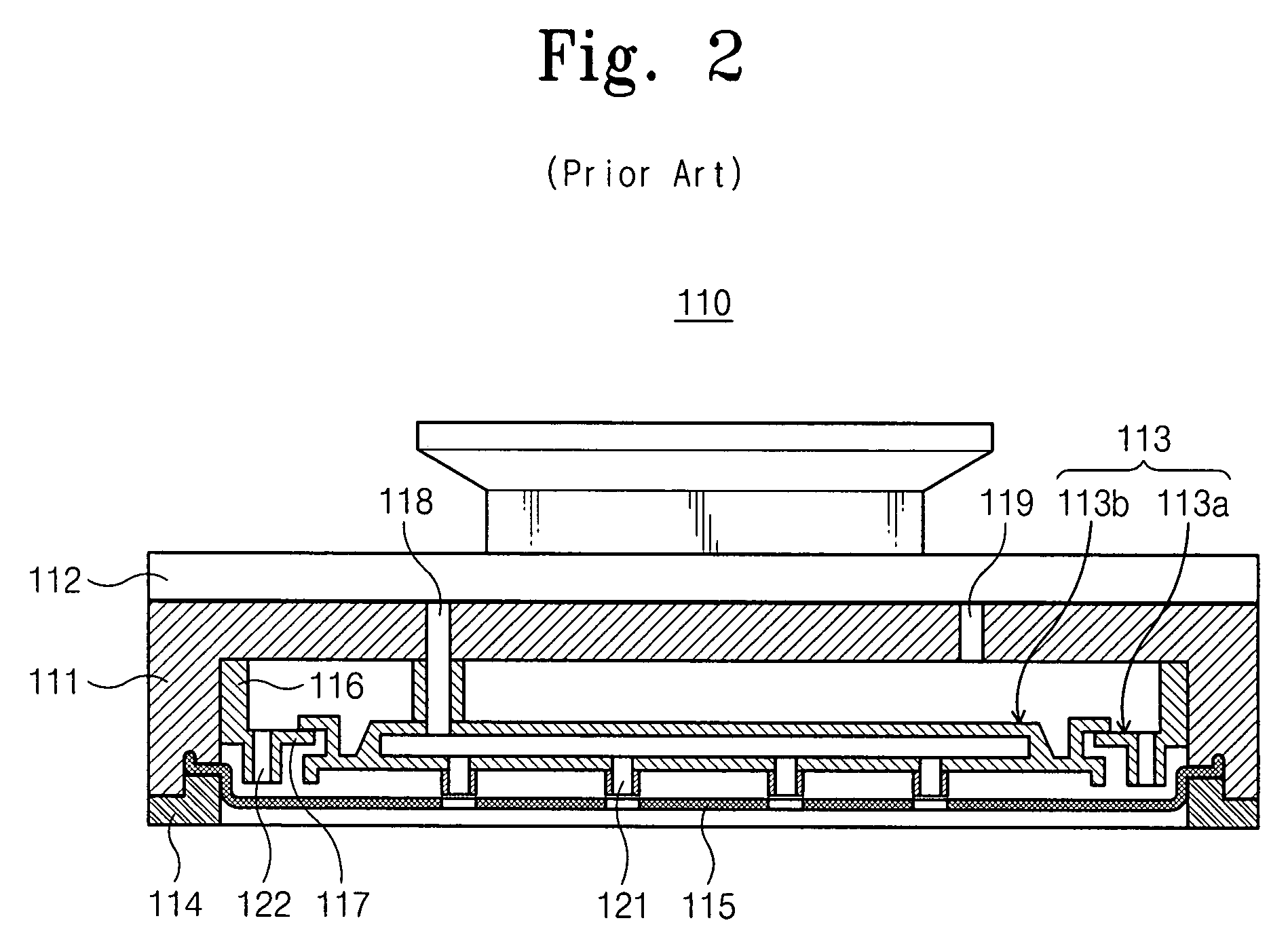
[0010]According to some embodiments of the present invention, a chemical mechanical polishing apparatus includes a platen, a polishing pad affixed to a surface of the platen, and a polishing head configured to retain and rotate a wafer while pressing a surface of the rotating wafer against the polishing pad. A first portion of the polishing pad that engages the polishing head proximate the edge of the wafer provides less rigidity than a second portion of the polishing pad that engages a portion of the surface of the wafer. For example, the platen and the polishing head may interoperate such that the rotating wafer moves in a loop across a surface of the pad, and the first portion of the polishing pad may engage the polishing head proximate an innermost portion of the loop.
[0018]According to some method embodiments of the present invention, a chemical mechanical polishing method includes pressing a surface of a rotating wafer on to a polishing pad and providing less rigidity in the pad where the pad engages the polishing head proximate an edge of the wafer than where the pad engages a portion of the surface of the wafer. The method may further include moving the rotating wafer in a loop across a surface of the pad, and providing less rigidity in the pad where the pad engages the polishing head proximate the edge of the wafer may include providing less rigidity proximate an innermost portion of the loop. For example, providing less rigidity in the pad where the pad engages the polishing head proximate an edge of the wafer may include providing a recess in the polishing pad and / or the platen proximate a locus of movement of the edge of the wafer across the polishing pad.

Problems solved by technology

Because of the nature of the polishing process, CMP pads wear as they are used.
For example, a pad design that tears or develops a significantly non-uniform surface may provide unacceptably non-uniform polishing results or may need to be replaced more often than desired.

Method used


Image

  • Chemical mechanical polishing apparatus and methods using a polishing surface with non-uniform rigidity
  • Chemical mechanical polishing apparatus and methods using a polishing surface with non-uniform rigidity
  • Chemical mechanical polishing apparatus and methods using a polishing surface with non-uniform rigidity

Examples


Embodiment Construction

[0034]The present invention now will be described more fully hereinafter with reference to the accompanying drawings, in which typical and exemplary embodiments of the invention are shown. This invention may, however, be embodied in many different forms and should not be construed as limited to the embodiments set forth herein. Rather, these embodiments are provided so that this disclosure will be thorough and complete, and will fully convey the scope of the invention to those skilled in the art.

[0035]In the drawings, the thickness of layers and regions are exaggerated for clarity. It will be understood that when an element such as a layer or region is referred to as being “on” another element, it can be directly on the other element or intervening elements may also be present. Furthermore, relative terms, such as “beneath,” may be used herein to describe one element's relationship to another elements as illustrated in the drawings. It will be understood that relative terms are inte...


PUM

PropertyMeasurementUnit
widthaaaaaaaaaa
diameteraaaaaaaaaa
radiusaaaaaaaaaa

Abstract

A chemical mechanical polishing apparatus includes a platen, a polishing pad affixed to a surface of the platen, and a polishing head configured to retain and rotate a wafer while pressing a surface of the rotating wafer against the polishing pad. A first portion of the polishing pad that engages the polishing head proximate the edge of the wafer provides less rigidity than a second portion of the polishing pad that engages a portion of the surface of the wafer. For example, the polishing pad and / or the platen may have a recess or other cushioning structure positioned proximate a locus of movement of a portion of the polishing head that supports the edge of the wafer.

Description

RELATED APPLICATION[0001]This application claims priority under 35 U.S.C. § 119 to Korean Patent Application 10-2003-77637 filed on Nov. 4, 2003, the contents of which are herein incorporated by reference in their entirety.BACKGROUND OF THE INVENTION[0002]The present invention relates to apparatus and methods for fabricating microelectronic devices, and more particularly, to polishing apparatus and methods.[0003]Fabrication of integrated circuit devices, such as memory devices, microprocessors, and the like, commonly involves the use of chemical mechanical polishing (CMP) to remove materials from a wafer surface and / or to planarize the surface of the wafer before building up additional structures. Generally, CMP involves rubbing the surface of the wafer against a pad made of a resilient material, such as polyurethane, in the presence of a chemical slurry to remove material, such as a metallization layer, deposited on the wafer surface. The pad and / or the slurry may include abrasives...

Claims


Application Information

Patent Timeline
Patent Type & Authority Patents(United States)
IPC IPC(8): B24B1/00B24B37/04B24B41/06H01L21/304B24D13/14
CPCB24B37/30B24B37/26H01L21/304
Inventor YUN, HYUN JOOLIM, YOUNG SAMBOO, JAE PIL
Owner SAMSUNG ELECTRONICS CO LTD
Why Eureka
Try Eureka