Bone fixation system with low profile fastener

a low-profile, bone fixation technology, applied in the field of orthopedic surgery, can solve the problems of stripping the purchase between the bones, adding torque to the assembly,

Active Publication Date: 2006-08-15
SPINAL
View PDF63 Cites 246 Cited by
  • Summary
  • Abstract
  • Description
  • Claims
  • Application Information

AI Technical Summary

Problems solved by technology

All these prior art spinal fixation devices result in additional torque applied to the assembly, and thereby to the bone screw, to tighten and lock the rod to each of the bone screws.
The additional load may strip the purchase between the bone and the threads of the bone screw.

Method used


Image

  • Bone fixation system with low profile fastener
  • Bone fixation system with low profile fastener
  • Bone fixation system with low profile fastener

Examples


Embodiment Construction

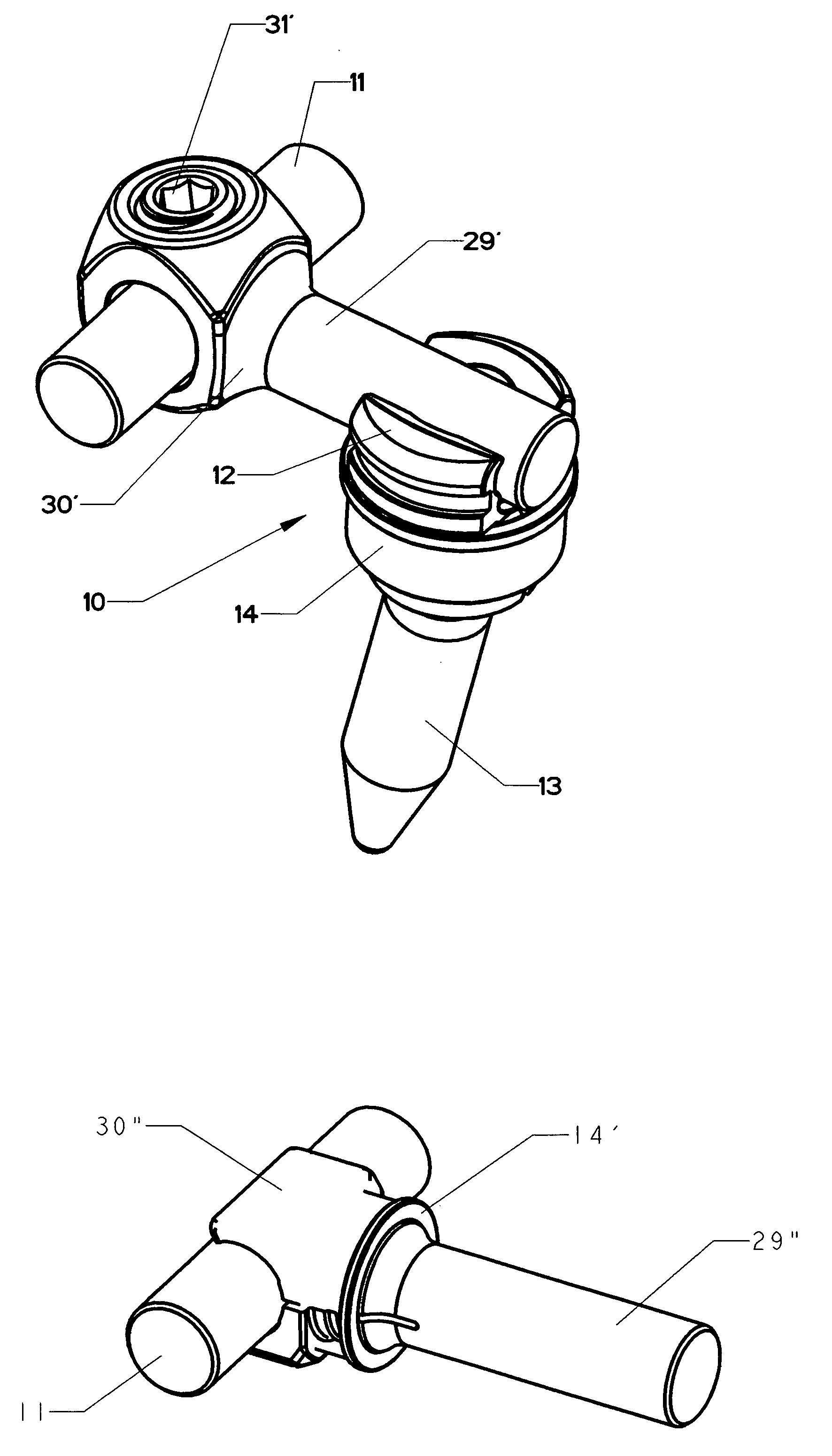
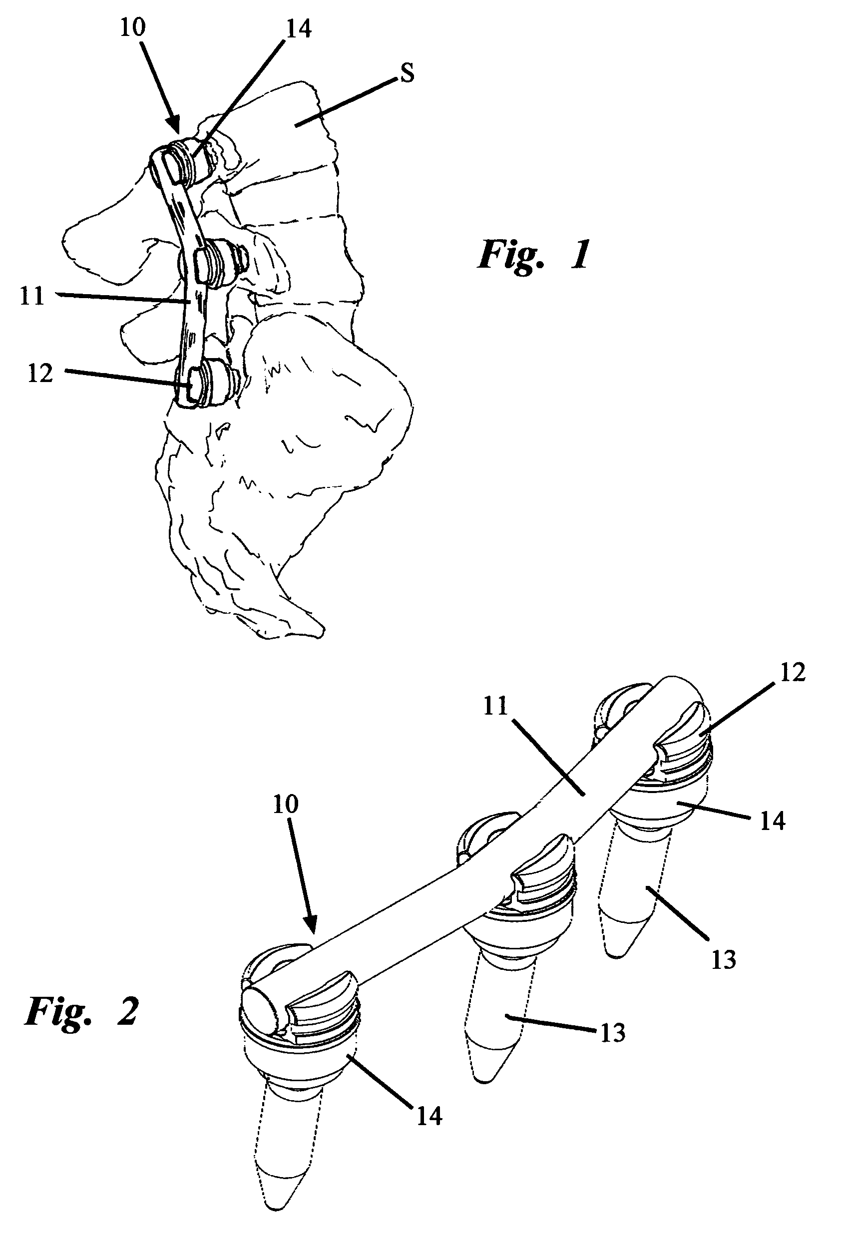
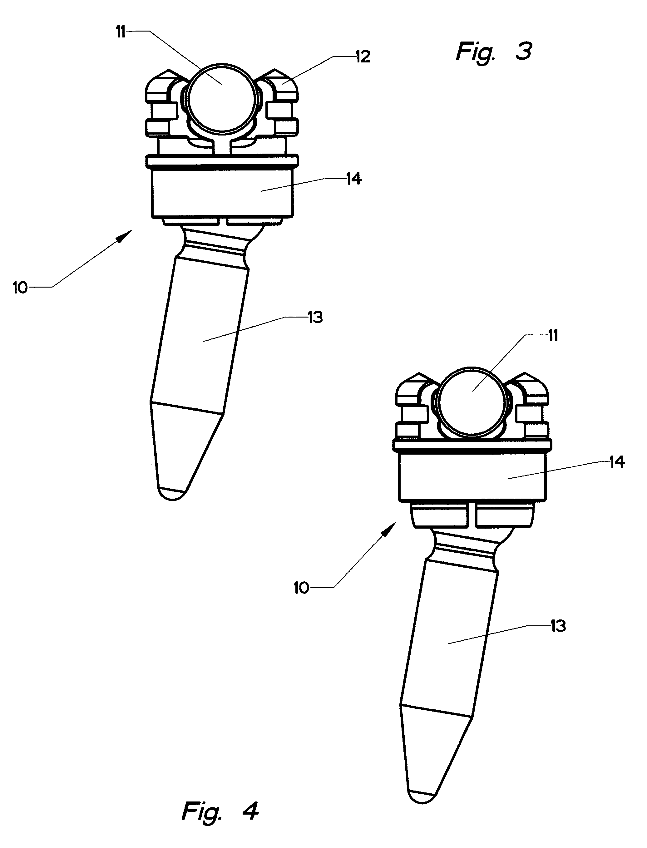
[0034]FIG. 1 illustrates a portion of the lumbar spine S with a unilateral orthopedic fixation device 10 in place to stabilize and fix the vertebra in relation to each other and the sacrum in order to maintain a more natural curvature. A bilateral installation can be used, if deemed necessary. As shown in more detail in FIG. 2, an elongated connector bar 11 spans the discontinuity between the vertebra and bone screws 13. As shown, the bar has a circular cross section however, other shapes may be used, such as shown for the link 29 in FIG. 13. The bone anchors have an exterior helical thread 60, shown in FIGS. 5–6, by which the bone screws 13 gain purchase in the cancellous bone through application of torque.

[0035]The torque is applied to the screws by the surgeon using a tool (not shown) that engages the recess 61 in the head 15 of the screw and rotates the screw about its longitudinal axis. The amount of torque is critical to installation and the long life of the prosthesis in that...


PUM


Abstract

A low profile orthopedic device is used to fix and stabilize bones to correct anomalies in skeletal structure occurring naturally or by trauma. Bone screws are screwed into bones by application of torque. Clamps are movably attached to the screws. Each clamp includes a compression ring. A connecting rod connects several screws through slots in the clamps. The clamps are tightened to hold the rod and the heads in a pre-selected position by linear movement of the compression rings.

Description

BACKGROUND OF THE INVENTION[0001]1. Field of the Invention[0002]This invention relates to orthopedic surgery and, in particular, to devices and prosthesis for stabilizing and fixing bones and joints of the body.[0003]2. Description of the Prior Art[0004]Published U.S. Application, US 2003 / 0149487 A1, published Aug. 7, 2003, teaches the use of a linear movement to apply compressive forces to connect components of an artificial hip joint.[0005]U.S. Pat. No. 6,626,906 issued Sep. 30, 2003 to Young teaches a spinal rod attached to a spinal anchor by a clamp. The clamp is tightened about the anchor by a collet screwed into the clamp. The rod is held in the clamp by a split ring that is reduced in size by the collet. The anchor is placed in the bone by torque and the collet is tightened by additional torque.[0006]U.S. Pat. No. 6,610,063 issued Aug. 26, 2003 to Kumar et al, U.S. Pat. No. 6,610,062 issued Aug. 26, 2003 to Bailey et al, U.S. Pat. No. 6,565,565 issued May 20, 2003 to Yuan et ...

Claims


Application Information

Patent Timeline
Patent Type & Authority Patents(United States)
IPC IPC(8): A61B17/56A61B17/58A61B17/70A61FA61F2/30
CPCA61B17/7041A61B17/7037A61B17/7032A61B17/7011
Inventor DOUBLER, ROBERT L.HAMMILL, JOHN E.
Owner SPINAL
Why Eureka
Try Eureka