Monitoring device for melting furnaces

a monitoring device and furnace technology, applied in the direction of furnace safety devices, blast furnace components, blast furnaces, etc., can solve the problems of increasing the transfer resistance at the flag, heavy damage to the system, endangering personnel, etc., to ensure the safe operation of the monitoring device, increase the electric resistance, and ensure the effect of reliable and continuous monitoring of the function of the monitoring devi

Inactive Publication Date: 2006-08-15
WIELAND WERKE AG
View PDF6 Cites 16 Cited by
  • Summary
  • Abstract
  • Description
  • Claims
  • Application Information

AI Technical Summary

Benefits of technology

[0015]Through the operation for many weeks under the effects of heat, a monitoring device must be permanently mounted on the furnace. This occurs advantageously on the surface of a refractory liner, which surface faces away from the crucible filled with melt. This surface must be configured to have a magnitude of electric resistance corresponding to the ohmic resistor R. The refractory liner in a preferred embodiment is made of a ceramic material, thus causing the electric resistance of the refractory liner to be a multiple of the ohmic resistor R. This value assures a safe operation of the monitoring device. The crucible filled with melt is in an alternative embodiment a part of a conductor section. Particularly suited for this are electrically conducting electric or clay-graphite crucibles.
[0016]The respective conductor sections are longer in larger furnace systems, thus increasing their electric resistance to a considerable measure. It is advantageous in such cases to arrange several monitoring devices around the crucible filled with melt. Each individual monitoring device can also take on different tasks so that when melt runs out, for example, in connection with a special danger to personnel, the furnace is immediately switched off; in case of a run out without an immediate danger the furnace performance is at another area continuously controlled down.
[0017]The advantages achieved with the invention are in particular that in the event of a break of the cable there occurs a change of the display and thus a reliable and continuous monitoring of the function of the monitoring device is assured. In particular the system damages caused by a crack in the crucible are minimized and personnel is protected. Beyond already existing systems, the monitoring device functions in particular in furnaces with electric or clay-graphite crucibles since here the distinct dependency of the temperature of the resistance needed in other systems is unnecessary. Also additional devices such as, for example, contact flags, which are susceptible to trouble, are no longer needed. Melting furnaces can be monitored continuously and reliably for a break out of melt caused by a crack in the crucible and the safety of the system can be increased.

Problems solved by technology

The cracking of a crucible can cause heavy damage to the system in induction furnaces, and in addition can endanger personnel.
The disadvantage of this system is that when the contact in the circuit is lost a change is not displayed, for example, due to a cable disruption caused by shrinkage of the crucible or due to oxidation of the stainless steel flag, which results in an increase of the transfer resistance at the flag.
This results in the monitoring device becoming ineffective since the resistance display remains at infinite even when a melt tongue touches the warning system.
However, this works only to a limited degree in particular in furnaces with electric or clay-graphite crucibles since the explicit temperature dependency of the resistance does not exist here.

Method used


Image

  • Monitoring device for melting furnaces
  • Monitoring device for melting furnaces
  • Monitoring device for melting furnaces

Examples


Embodiment Construction

[0022]Corresponding parts in all figures are identified with the same reference numerals.

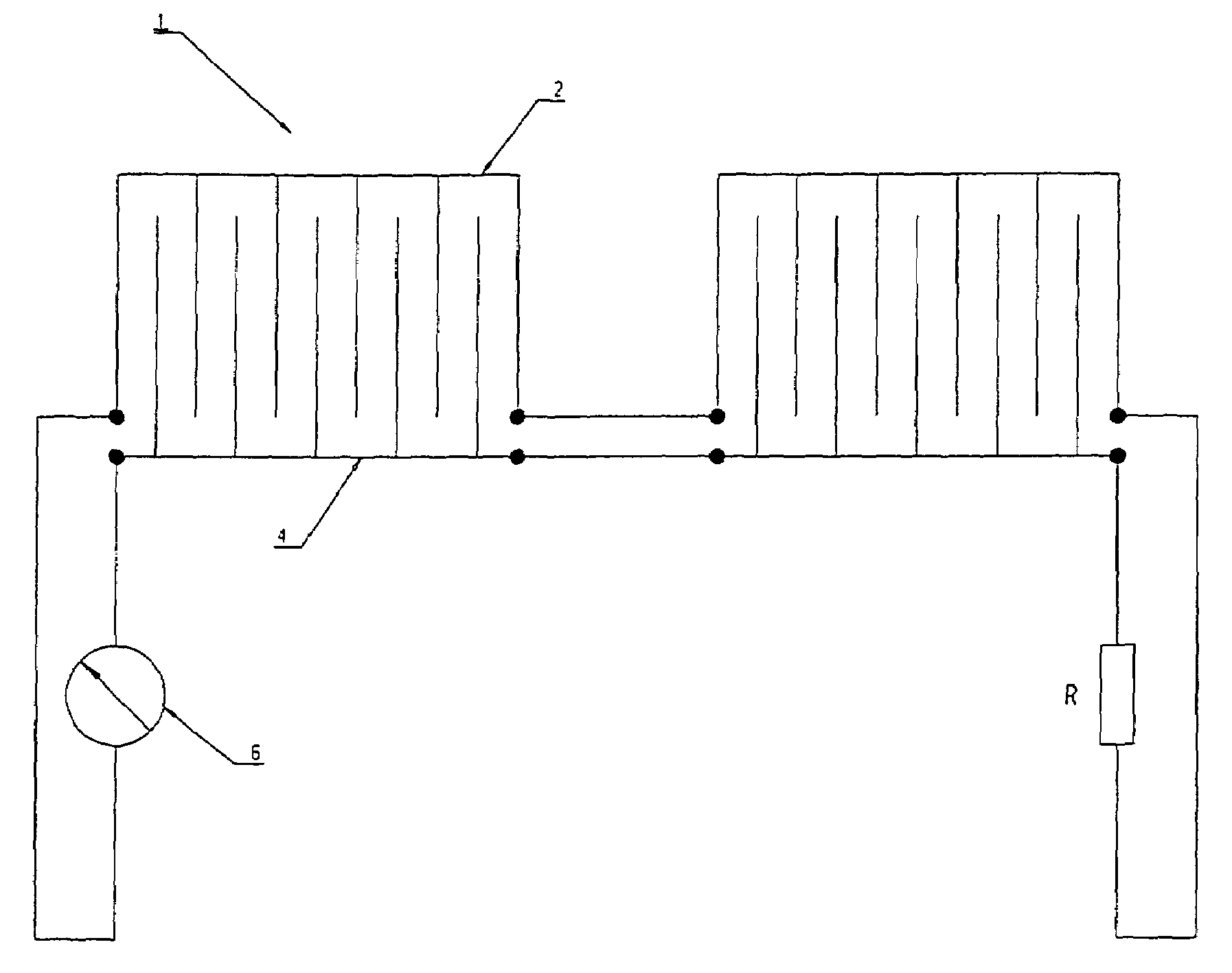
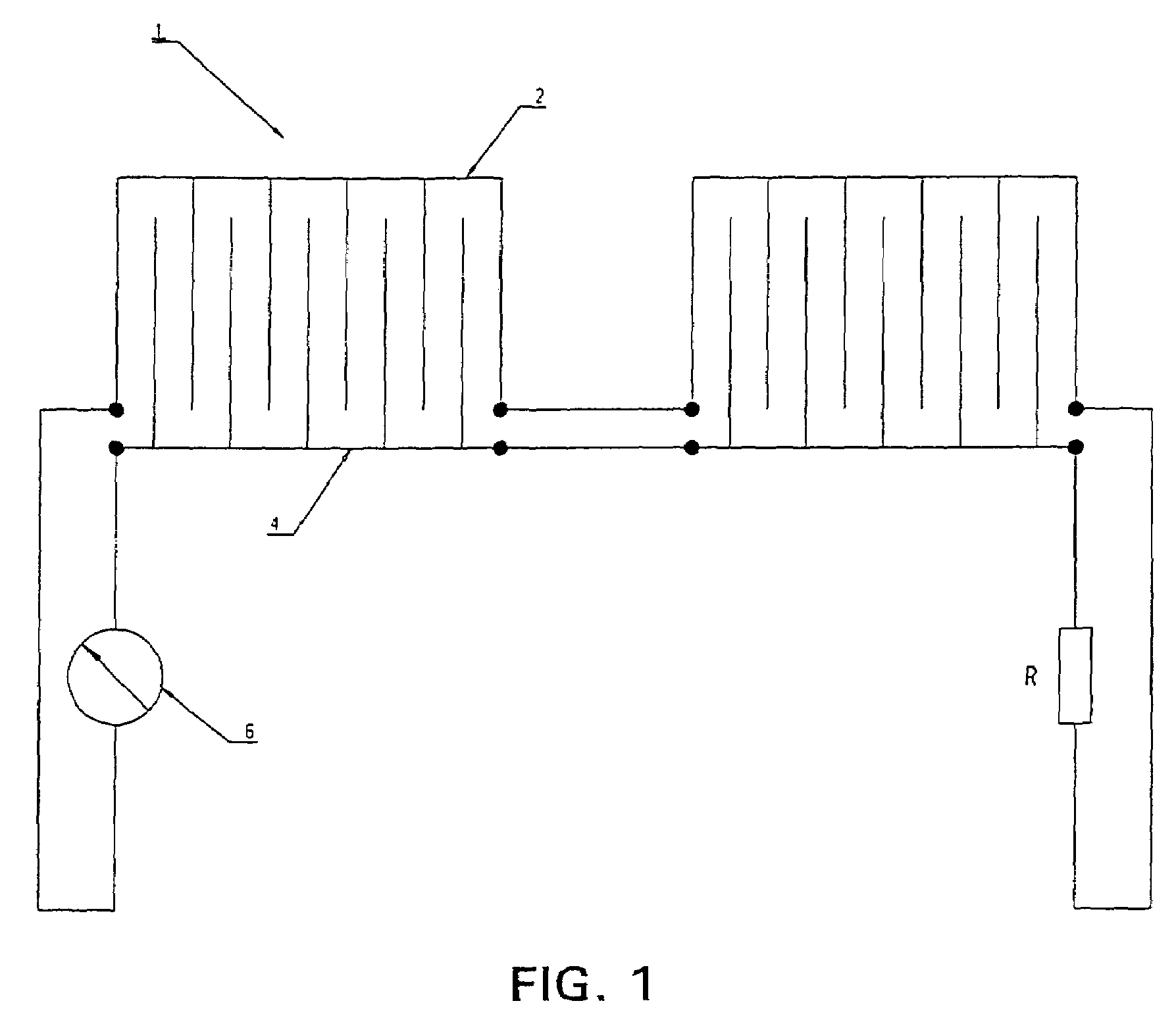
[0023]The monitoring device 1 according to FIG. 1 includes a first conductor section 2 which is connected in series through an ohmic resistor R to a second conductor section 4, and forms a closed circuit having a measuring / displaying device 6. Both conductor sections have a comb-shaped design and are interleaved with one another so that the conducting paths are arranged directly adjacent, however, electrically isolated from one another. The comb-shaped area of the conductor sections represents the actual sensor region for the running out melt. The directly adjacent conductors are short-circuited as soon as metallic melt running out from a crucible contacts both. The ohmic resistor R, which is connected in series, lies in an area where it is not directly subjected to the high furnace temperature.

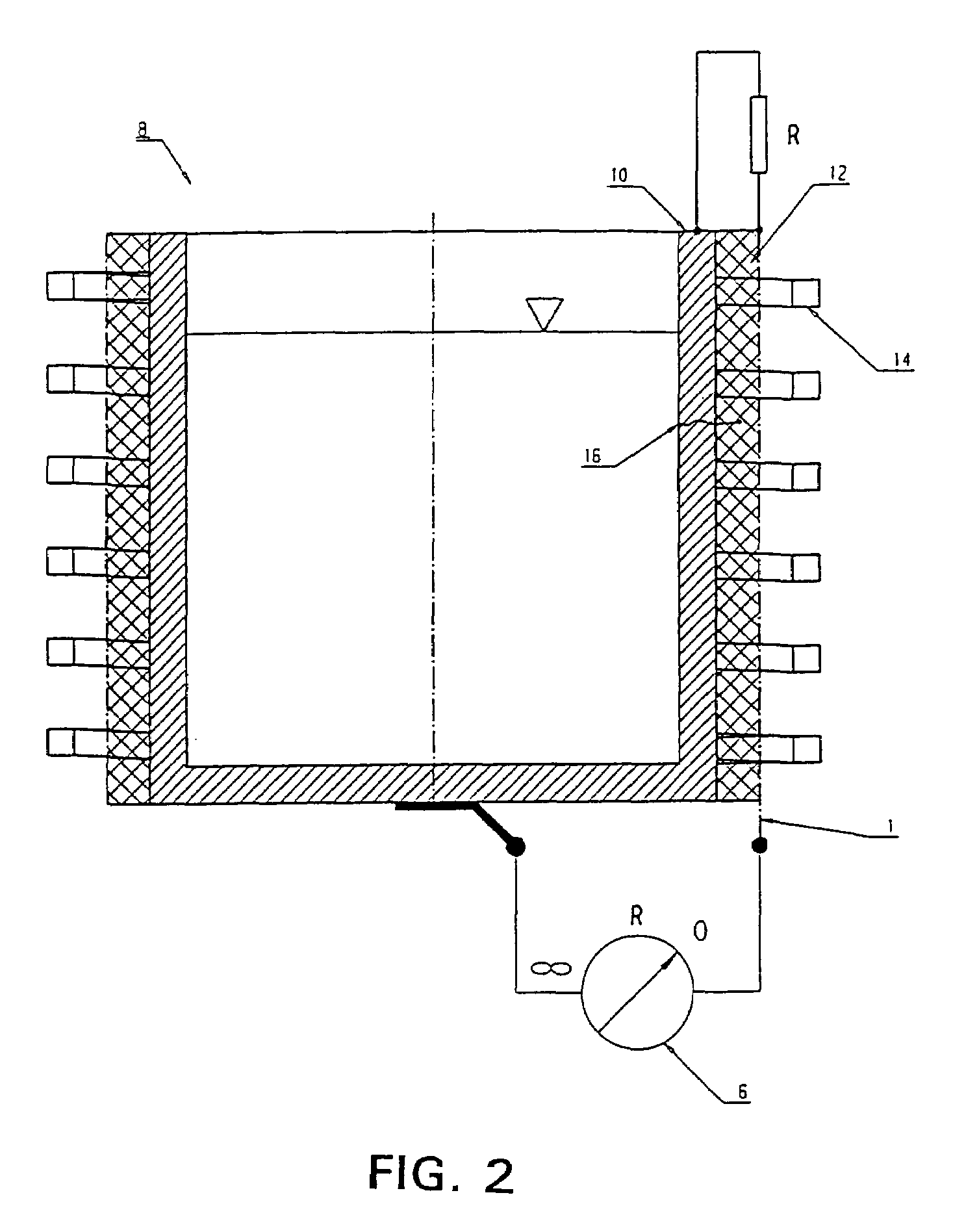
[0024]The exemplary embodiment according to FIG. 2 illustrates a melting furnace 8, designed as an ind...


PUM

PropertyMeasurementUnit
temperatureaaaaaaaaaa
resistanceaaaaaaaaaa
ohmic resistanceaaaaaaaaaa

Abstract

Cracking of a crucible can cause heavy damage to the system in melting furnaces. A reliable monitoring of threatening breaking out of the melt is therefore needed. For this purpose a monitoring device for melting furnaces is provided to monitor the breaking out of melt and includes a closed circuit consisting of several conductor sections with at least a partially conducting surface and a measuring/displaying device. A first conductor section is series connected through an ohmic resistor R to a second conductor section. The first conductor section is arranged directly adjacent, however, electrically isolatingly spaced from and with respect to the second conductor section.

Description

FIELD OF THE INVENTION[0001]The invention relates to a monitoring device for melting furnaces to monitor the breaking out of melt, in particular for coreless or channel-type induction furnaces, including a closed circuit consisting of several conductor sections with at least a partially conducting surface and a measuring / indicating device.BACKGROUND OF THE INVENTION[0002]The cracking of a crucible can cause heavy damage to the system in induction furnaces, and in addition can endanger personnel. Various systems are already being used for the timely supply of information regarding threatening breaking out of melt.[0003]Usually in the simplest case the contact of melt with the coil is indicated through ground fault. Warning systems installed in front of the coil, for example on an electrically insulating refractory liner applied to the coil, create a warning prior to the running out melt contacting the coil. The control and design of the warning systems exist in various forms. Simple ...

Claims


Application Information

Patent Timeline
Patent Type & Authority Patents(United States)
IPC IPC(8): C21D11/00C21B7/24F27B14/20F27D21/00G01N27/20
CPCF27B14/20G01N27/205F27D21/0021F27D2021/0085
Inventor MUELLER, HILMAR R.THIESS, HORST
Owner WIELAND WERKE AG
Why Eureka
Try Eureka