
Optoacoustic measuring arrangement and use thereof

a technology of optoacoustic and measuring arrangement, which is applied in the direction of fire alarms, instruments, fire alarm radiation actuation, etc., can solve the problem that the opto-acoustic principle has not been used for smoke detection

Inactive Publication Date: 2006-08-15
SIEMENS BUILDING TECHNOLOGIES +1
View PDF13 Cites 13 Cited by
  • Summary
  • Abstract
  • Description
  • Claims
  • Application Information

AI Technical Summary

Benefits of technology

[0008]These drawbacks are solved according to the present invention, namely an opto-acoustic measuring arrangement of the type described at the outset and wherein the measuring cell and the reference cell are open at least at one end to the gas and / or aerosol to be detected. This arrangement eliminates the need to filter the gas / aerosol being investigated. Normally the sensor signal is zero, and a signal which requires only a relatively simple electronic circuit for its processing is produced in the measuring cell, and then only in the presence of aerosol or a combustible gas which absorbs the radiation emitted by the radiation source.
[0014]The present invention further includes a smoke alarm application for the novel measuring arrangement. Here the measuring arrangement has a measuring cell which is exposed to radiation having a wavelength at which the aerosol to be detected is absorbed, and as a result, an opto-acoustic effect is produced.
[0015]A fire hazard alarm is another application for the measuring arrangement of the present invention. Here the measuring arrangement has a measuring cell which is exposed to radiation having a wavelength at which a combustible or explosive substance to be detected is absorbed, and as a result, an opto-acoustic effect is produced.
[0017]A combined fire alarm and fire hazard alarm is another application of the novel measuring arrangement. Here the measuring arrangement has two measuring cells, one of which is exposed to radiation having a wavelength at which the aerosol or a combustible gas to be detected is absorbed, and the other of which is exposed to radiation having a wavelength at which a combustible or explosive substance to be detected is absorbed, and as a result, an opto-acoustic effect is produced.

Problems solved by technology

Nevertheless, the opto-acoustic principle has not been used for smoke detection, primarily because of the additional expense attributable to air filtering, and the correction of the signal magnitude.

Method used


Image

  • Optoacoustic measuring arrangement and use thereof
  • Optoacoustic measuring arrangement and use thereof
  • Optoacoustic measuring arrangement and use thereof

Examples


Embodiment Construction

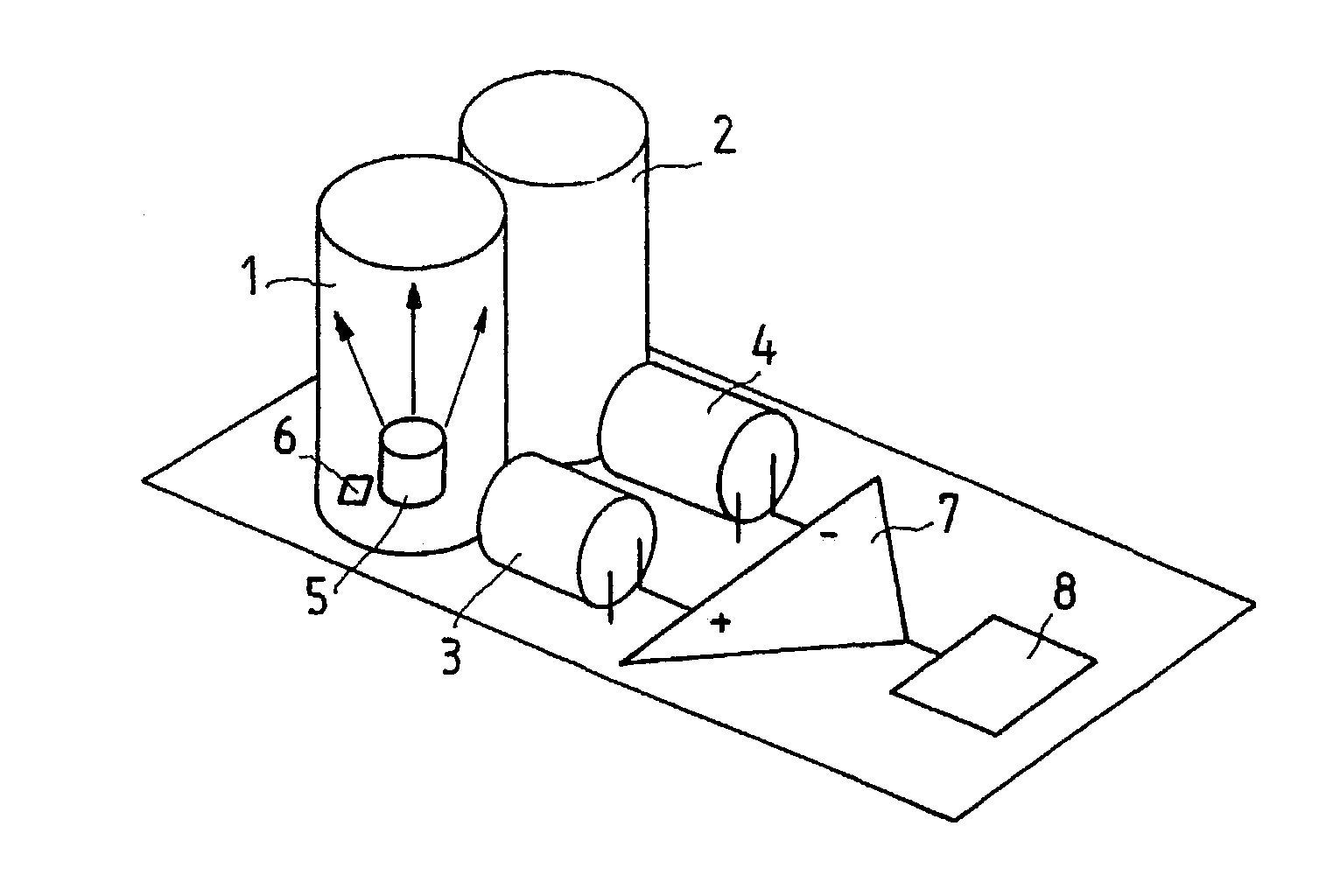
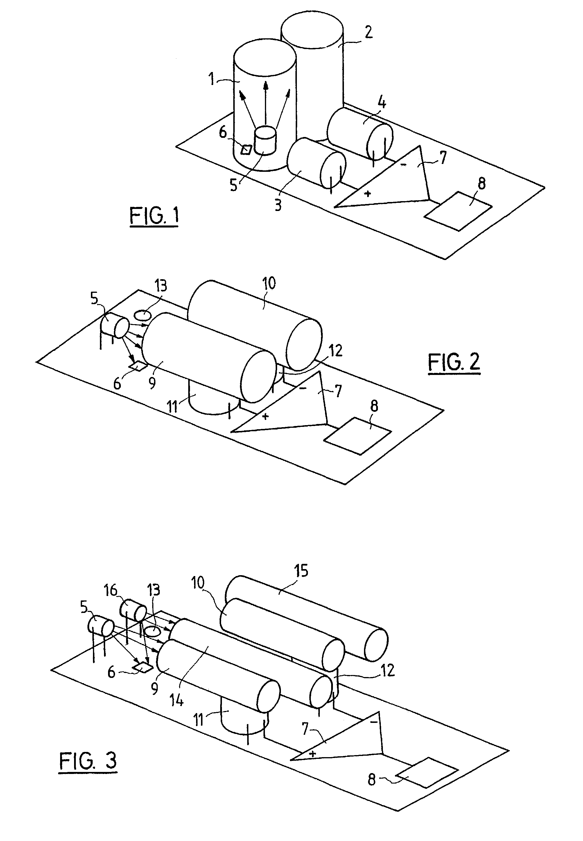
[0022]The opto-acoustic measuring arrangement illustrated in FIG. 1 is a resonant, dual sensor, open at one end, with a tubular measuring cell 1 and a tubular reference cell 2, to each of which a microphone 3 and 4, respectively, is assigned. Furthermore, a radiation source 5, for example an LED, is provided, which exposes the inner space of the measuring cell 1 with radiation of a specific wavelength. In addition to the radiation source 5, a first photocell 6 is disposed for monitoring the intensity of the radiation emitted by the radiation source 5. The outputs of the two microphones 3 and 4 are fed to a differential amplifier 7 in which the microphone signals are subtracted from each other. The output signal of the differential amplifier 7 is fed to a phase-sensitive rectifier (lock-in) 8.

[0023]Tubes open at one end, with a length “I” have a resonant frequency Vk, which is given by the formulae:

[0024]υ⁢⁢k=2⁢k+14⁢l⁢c,

where (k=0,1,2,3, . . . ; c=velocity of sound air)

With a length ...


PUM


Abstract

The measuring arrangement contains a measuring cell and a reference cell, respectively, and microphones assigned to these cells, to which microphones an electronic evaluation circuit is connected and in which a subtraction of the signals of the microphones takes place, as well as a radiation source for applying a modulated signal to the measuring cell. The modulation frequency of the radiation source coincides with the resonant frequency of the measuring cell, and the measuring cell and the reference cell are open at at least one end to the gas to and / or aerosol to be detected. The measuring arrangement is used as smoke alarm, gas alarm, fire hazard alarm or as combined smoke and gas alarm, wherein each of the measuring cells is exposed to a radiation of a wavelength at which a relevant substance to be detected is absorbent and an opto-acoustic effect is produced as a result.

Description

CROSS-REFERENCE TO RELATED APPLICATIONS[0001]This is a national application for International Application No. PCT / CH01 / 00588 which was filed on Oct. 1, 2001 and which published in German on Apr. 18, 2002, which in turn claims priority from 00121937.7, which was filed on Oct. 9, 2000, and 896 / 01, which was filed on May 15, 2001, of which the following is aSUBSTITUTE SPECIFICATION[0002]1. Field of the Invention[0003]The present invention relates to an opto-acoustic measuring arrangement for the detection of gases and / or aerosols. The arrangement includes a measuring cell and a reference cell, microphones, respectively, assigned to each cell, an electronic evaluation circuit connected to the microphones in which a subtraction of the signals of the microphones occurs, and a radiation source for applying a modulated signal to the measuring cell. The modulation frequency of the radiation source coincides with the resonant frequency of the measuring cell.[0004]2. Background of the Inventio...

Claims


Application Information

Patent Timeline
IPC IPC(8): G08B17/10G01N21/17
CPCG01N21/1702G01N2021/1704G01N21/17
Inventor FORSTER, MARTINNEBIKER, PETER
Owner SIEMENS BUILDING TECHNOLOGIES
Learn More