
Polytopic multiplex holography

a polytopic multiplex and holography technology, applied in the field of polytopic multiplex holography, can solve the problems of limited stack spacing, increased spatial stack size, and limited minimum distance between stacks

Active Publication Date: 2006-08-15
AKONIA HOLOGRAPHICS
View PDF9 Cites 124 Cited by
  • Summary
  • Abstract
  • Description
  • Claims
  • Application Information

AI Technical Summary

Benefits of technology

[0009]This invention describes a new holographic recording technique referred to herein as Polytopic multiplexing. This multiplexing technique allows holograms to be spatially multiplexed with partial spatial overlap between neighboring stacks of holograms. Each individual stack can additionally take full advantage of an alternate multiplexing scheme such as angle, wavelength, phase code, peristrophic, correlation, or fractal multiplexing. An amount equal to the beam waist o

Problems solved by technology

However, as discussed above, close spacing of stacks is limited.
Additionally, the divergence of a beam can limit the minimum distance between stacks.
Unfortunately, if the media is made thicker the spatial stack size increases due to the increased divergence of the beam.
Thus, density cannot be increased significantly by increasing the material thickness once the saturation thickness is reached.
This increases the density of the stacks but many fewer holograms can be recorded in a stack, which very significantly reduces the density gains of overlapping the stacks.
When multiplexing holograms, however, the dynamic range of the holographic media can be a limiting factor.

Method used


Image

  • Polytopic multiplex holography
  • Polytopic multiplex holography
  • Polytopic multiplex holography

Examples


Embodiment Construction

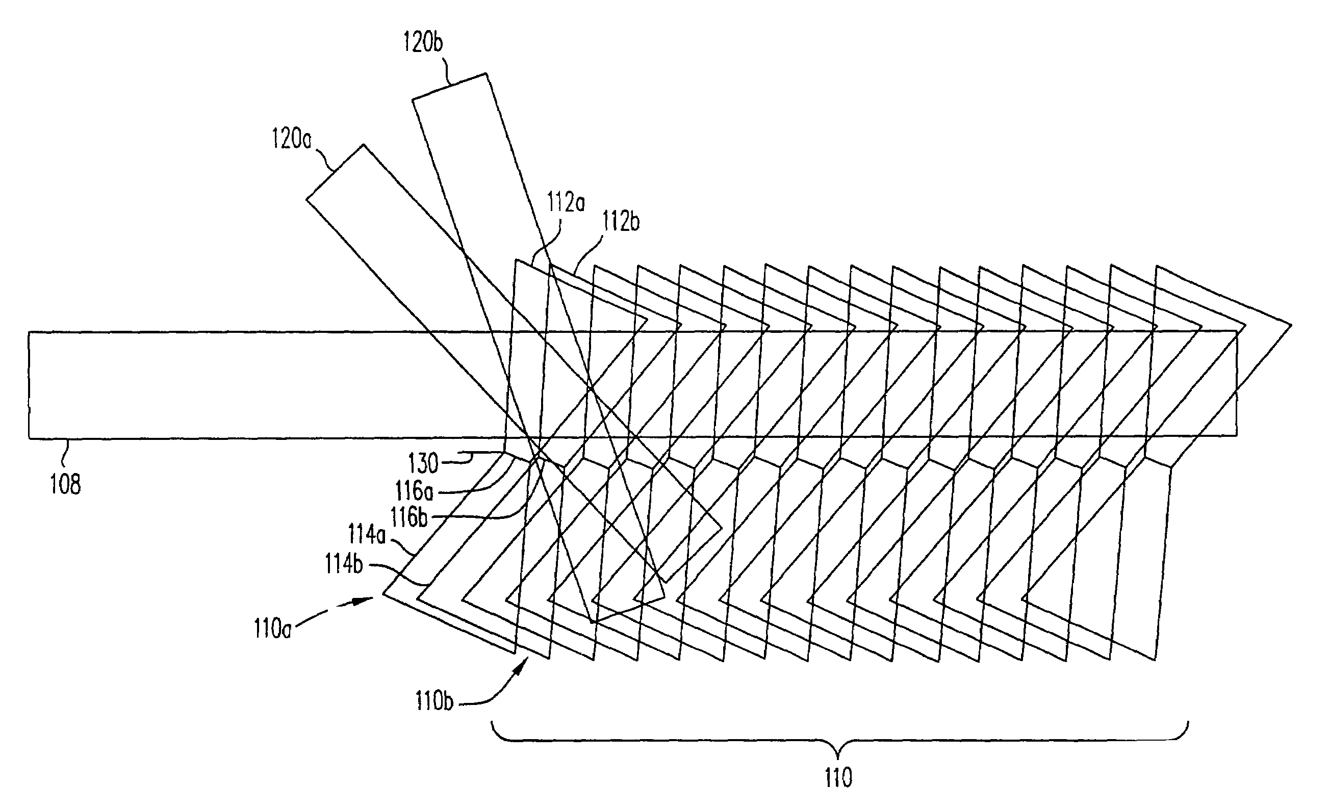
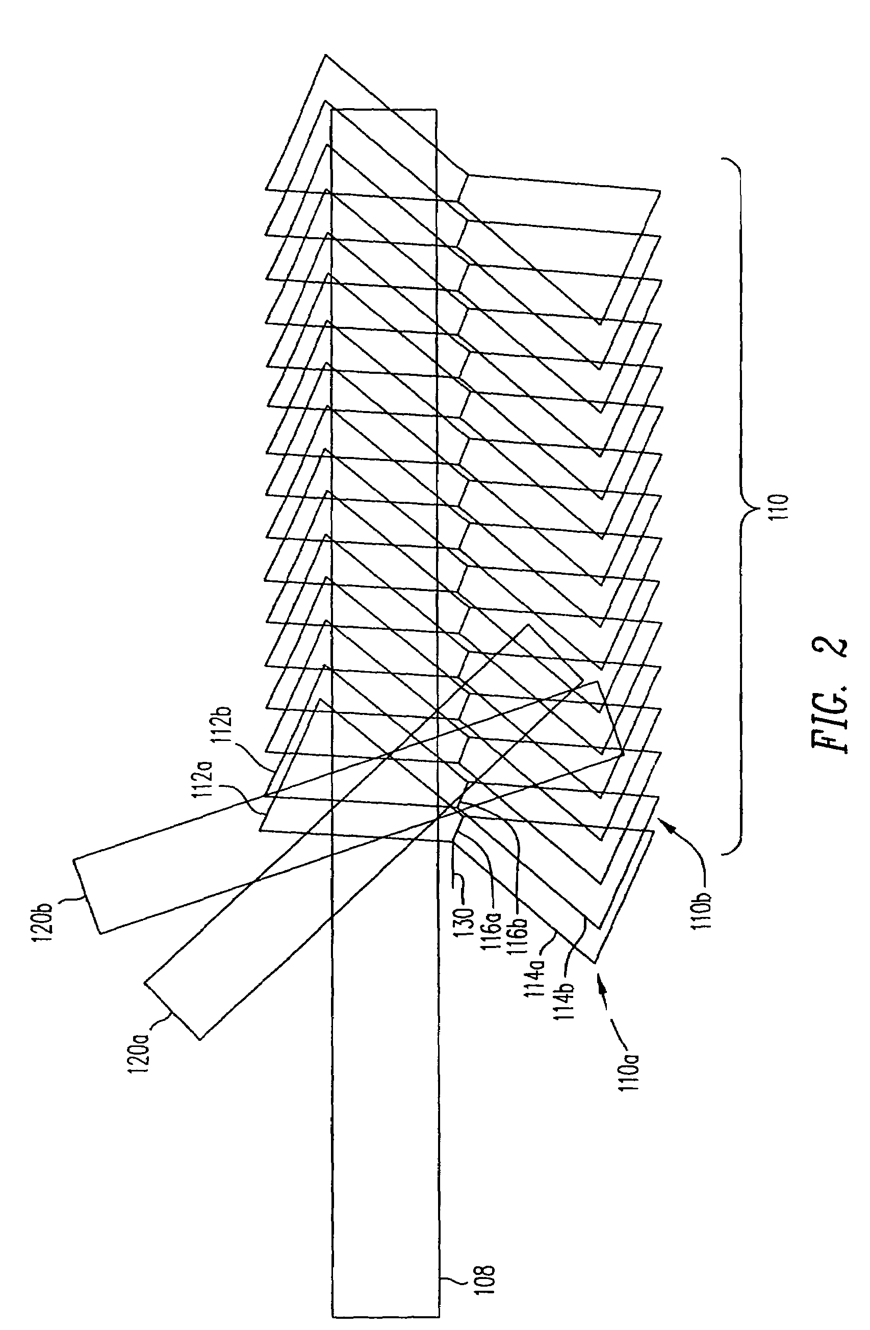
[0026]A method of increasing the density of holograms stored in a holographic media in accordance with the present invention is illustrated in FIG. 2. FIG. 2 illustrates a holographic media 108 in which a plurality a holograms are generated by a plurality of signal beams 110. Each of the plurality of signal beams 110 include an incoming converging cone, and outgoing diverging cone and a beam waist. In particular, a first signal beam 110a includes a first incoming converging cone 112a, and a first outgoing diverging cone 114a and a first beam waist 116a. As used herein, the “waist” of a beam can indicate either the beams Fourier transform plane or image plane. In FIG. 2, beam waist 116a can be either the Fourier transform plane or the image plane. FIG. 2 also shows a first reference beam 120a and a second reference beam 120b. As is understood in the art, signal beam 110a and first reference beam 120a can generate a first hologram. A first additional signal beam (not shown) which can ...


PUM

PropertyMeasurementUnit
Sizeaaaaaaaaaa
Transmissionaaaaaaaaaa
Dimensionaaaaaaaaaa

Abstract

Disclosed is a multiplexing method and apparatus that allows holograms to be spatially multiplexed with partial spatial overlap between neighboring stacks of holograms. Each individual stack can additionally take full advantage of an alternate multiplexing scheme such as angle, wavelength, phase code, peristrophic, or fractal multiplexing, for example. An amount equal to the beam waist of the signal beam writing a hologram separates individual stacks of holograms. Upon reconstruction, a hologram and its neighbors will all be readout simultaneously. An filter is placed at the beam waist of the reconstructed data such that the neighbors that are read out are not transmitted to the camera plane. Alternatively, these unwanted reconstructions can be filtered out with an angular filter at an intermediate plane in the optical system that has a limited angular passband.

Description

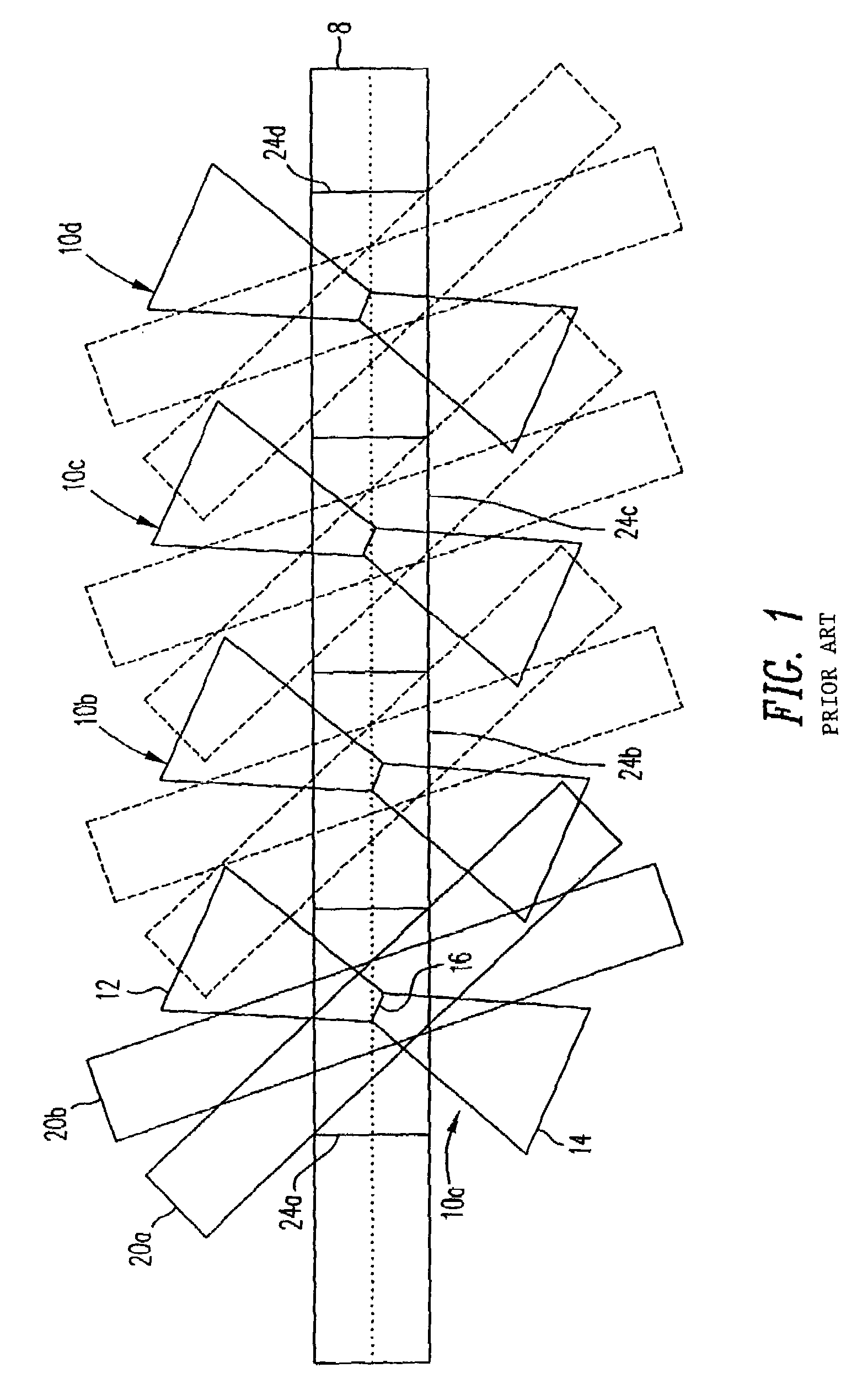
CROSS REFERENCE TO RELATED APPLICATIONS[0001]The present application claims priority to U.S. Provisional Patent Application No. 60 / 453,529, filed Mar. 10, 2003 entitled “A Method for Overlapping Holograms Using Location Based Filtering to Separate Out the Signal” which is incorporated by reference in its entirety.BACKGROUND OF THE INVENTION[0002]Multiplexing holograms means to store multiple holograms in the same volume or nearly the same volume. Typically, this is done by varying an angle, wavelength, phase code, or some other system parameter in the recording and readout setup. Many of these methods rely on a holographic phenomena known as the Bragg effect in order to separate the holograms even though they are physically located within the same volume of media. Other multiplexing methods such as shift and, to some extent, correlation use the Bragg effect and relative motion of the media and input laser beams to overlap multiple holograms in the same volume of the media.[0003]Some...

Claims


Application Information

Patent Timeline
IPC IPC(8): G03H1/30G03H1/18G03H1/04G03H1/22G03H1/26G11B7/0065G11B7/135
CPCG11B7/0065G11B7/00772G11B7/083G03H1/2645G03H1/265G03H2001/2207G03H2001/2255G03H1/202G03H2223/21G03H2223/54G03H2223/55G03H1/0248C02F3/06C02F3/20B01F23/2312B01F23/231265
Inventor ANDERSON, KENNETH E.CURTIS, KEVIN R.
Owner AKONIA HOLOGRAPHICS
Learn More