Demagnetizing a head in a disk drive by increasing the frequency of an AC write signal while maintaining the write current amplitude

a technology of ac write signal and ac write current, which is applied in the field of disk drives, can solve the problems of reducing format efficiency, difficulty and expense of controlling the write current amplitude at the end of every write operation, etc., and achieve the effect of reducing the amplitude of the ac write signal

Active Publication Date: 2006-08-15
WESTERN DIGITAL TECH INC
View PDF7 Cites 149 Cited by
  • Summary
  • Abstract
  • Description
  • Claims
  • Application Information

AI Technical Summary

Benefits of technology

[0010]The present invention may also be regarded as a method of demagnetizing a head in a disk drive at the end of a write operation, the disk drive comprising a disk wherein the head is actuated over the disk. A write signal is applied to the head in order to write data to the disk during the write operation, wherein the write signal comprises a predetermined write current amplitude. The head is demagnetized at the end of the write operation by maintaining the write current amplitude while increasing a frequency of an AC write signal applied to the head over a predetermined demagnetization interval, wherein increasing the frequency of the AC write signal decreases an amplitude of the AC write signal when observed at the head.

Problems solved by technology

A problem with this technique, however, is the difficulty and expense involved with controlling the write current amplitude at the end of every write operation.
This gap is undesirable since it decreases the amount of disk space available for storing user data (i.e., decreases format efficiency).

Method used


Image

  • Demagnetizing a head in a disk drive by increasing the frequency of an AC write signal while maintaining the write current amplitude
  • Demagnetizing a head in a disk drive by increasing the frequency of an AC write signal while maintaining the write current amplitude
  • Demagnetizing a head in a disk drive by increasing the frequency of an AC write signal while maintaining the write current amplitude

Examples


Embodiment Construction

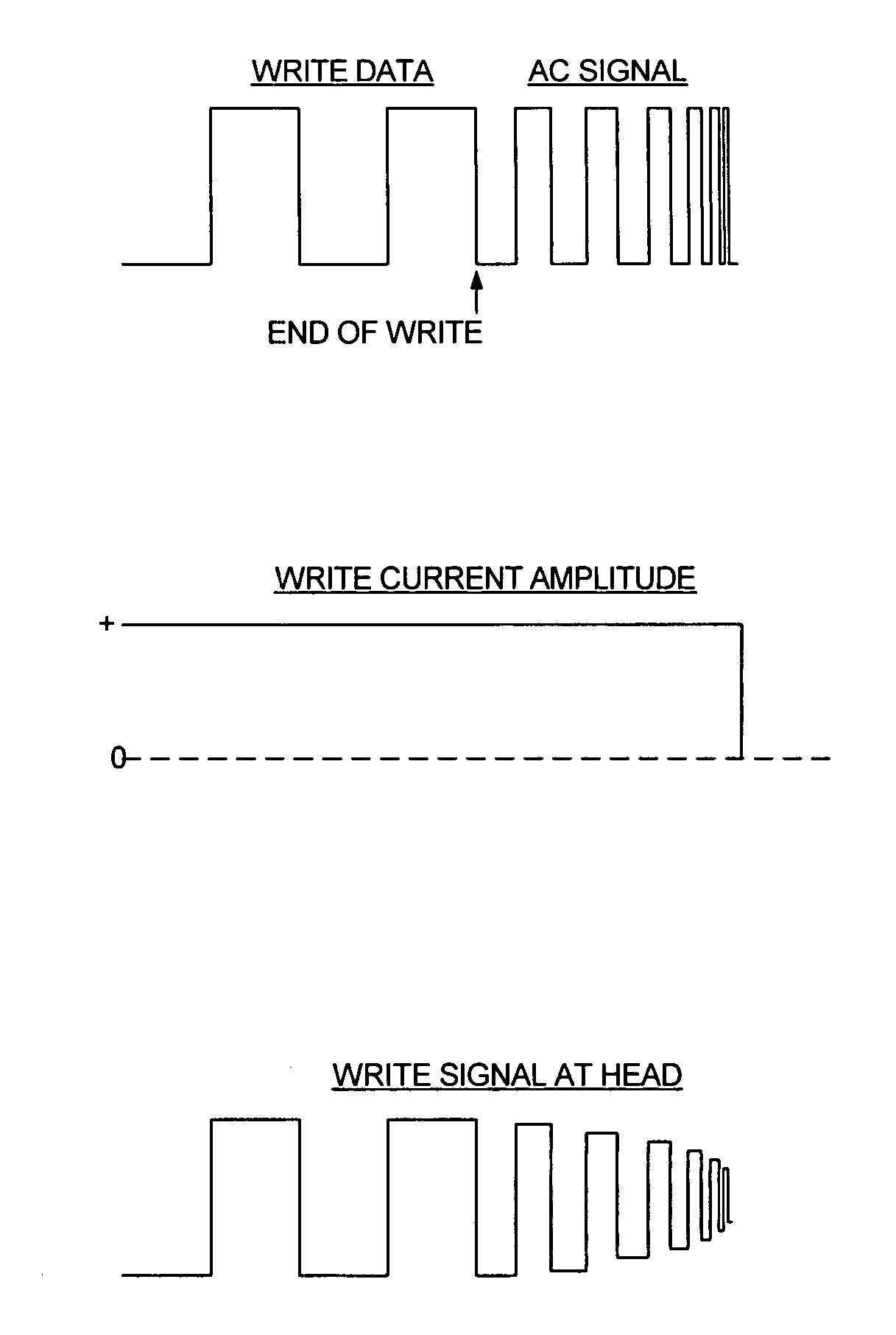
[0015]FIGS. 3A–3C and FIG. 4 show a disk drive according to an embodiment of the present invention comprising a disk 4 having a plurality of tracks 6, wherein each track comprises a plurality of data sectors and a head 16 is actuated over the disk 4. Write circuitry 24 applies a write signal 26 to the head 16 in order to write data (FIG. 3A) to a selected data sector during a write operation, wherein the write signal 26 comprises a predetermined write current amplitude (FIG. 3B). Control circuitry 28 demagnetizes the head 16 at the end of the write operation by maintaining the write current amplitude while increasing a frequency of an AC write signal (FIG. 3A) applied to the head 16 over a predetermined demagnetization interval, wherein increasing the frequency of the AC write signal decreases an amplitude of the AC write signal when observed at the head 16 (FIG. 3C).

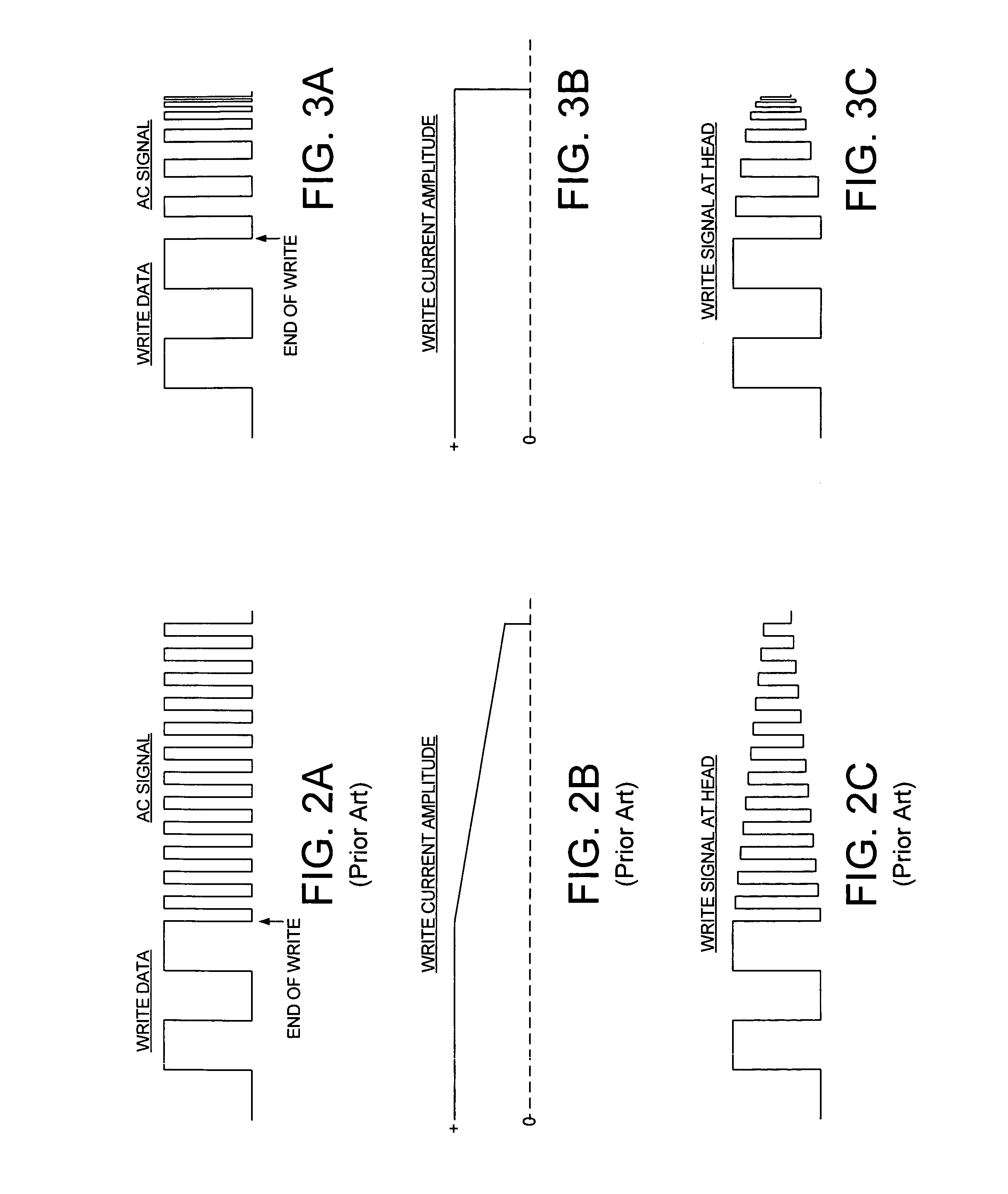
[0016]The aspects of the present invention are further understood by comparing the prior art technique shown in FIGS....


PUM

PropertyMeasurementUnit
current amplitudeaaaaaaaaaa
frequencyaaaaaaaaaa
magnetic fieldaaaaaaaaaa

Abstract

A disk drive is disclosed which demagnetizes the head after a write operation. Write circuitry applies a write signal to the head in order to write data to a selected data sector during a write operation, wherein the write signal comprises a predetermined write current amplitude. Control circuitry demagnetizes the head at the end of the write operation by maintaining the write current amplitude while increasing a frequency of an AC write signal applied to the head over a predetermined demagnetization interval, wherein increasing the frequency of the AC write signal decreases an amplitude of the AC write signal when observed at the head.

Description

BACKGROUND OF THE INVENTION[0001]1. Field of the Invention[0002]The present invention relates to disk drives. In particular, the present invention relates to demagnetizing the head in a disk drive by increasing the frequency of an AC write signal while maintaining the write current amplitude.[0003]2. Description of the Prior Art[0004]FIG. 1 is a prior art recording format showing a plurality of embedded servo sectors 20–2N recorded on the disk 4 of a disk drive which define a plurality of radially-spaced, concentric data tracks 6. Each data track 6 is partitioned into a plurality of data sectors wherein the servo sectors 20–2N are considered “embedded” in the data sectors. Each servo sector (e.g., servo sector 24) comprises a preamble 8 for synchronizing gain control and timing recovery, a sync mark 10 for synchronizing to a servo data field 12 comprising coarse head positioning information such as a Gray coded track addresses for use during seeking, and servo bursts 14 which provid...

Claims


Application Information

Patent Timeline
Patent Type & Authority Patents(United States)
IPC IPC(8): G11B15/04G11B19/04G11B5/02G11B5/03G11B5/09
CPCG11B5/465
Inventor HOGG, DENNIS W.
Owner WESTERN DIGITAL TECH INC
Why Eureka
Try Eureka