Dynamically selecting processor cores for overall power efficiency

a processor core and power efficiency technology, applied in the field of computer systems, can solve the problems of high performance, waste of computing resources and power to operate them, and inability to match software with modest resource requirements, so as to reduce power supply demands, save operating power, and save battery power in portable computers

Active Publication Date: 2006-08-15
HEWLETT PACKARD DEV CO LP
View PDF2 Cites 473 Cited by
  • Summary
  • Abstract
  • Description
  • Claims
  • Application Information

AI Technical Summary

Benefits of technology

[0010]An advantage of the present invention is that a system is provided that can conserve battery power in portable computers.
[0011]Another advantage of the present invention is that a method is provided for conserving operating power and reducing power supply demands.
[0012]These and other objects and advantages of the present invention will no doubt become obvious to those of ordinary skill in the art after having read the following detailed description of the preferred embodiment as illustrated in the drawing figures.

Problems solved by technology

Some waste can be involved in the mismatching of software with modest resource requirements on high performance hardware platforms.
When there is only one processor core available for all processing jobs, the waste of computing resources and power to operate them is unavoidable.
High performance hardware is usually associated with large demands on operating power input.
If such high performance is going to waste much of the time, the marginal operating power needed over more modest equipment is pure cost with no benefit.
In general, higher clock speeds and denser functionality has meant increased power consumption and hence dissipation.
Such power dissipation causes undesirable heating and, in battery-operated portable systems, leads to reduced battery life.
Constantly using a processor that uses a lot of power and that exceeds the needs of the application software can lead to significant power waste and costs.

Method used


Image

  • Dynamically selecting processor cores for overall power efficiency
  • Dynamically selecting processor cores for overall power efficiency
  • Dynamically selecting processor cores for overall power efficiency

Examples


Embodiment Construction

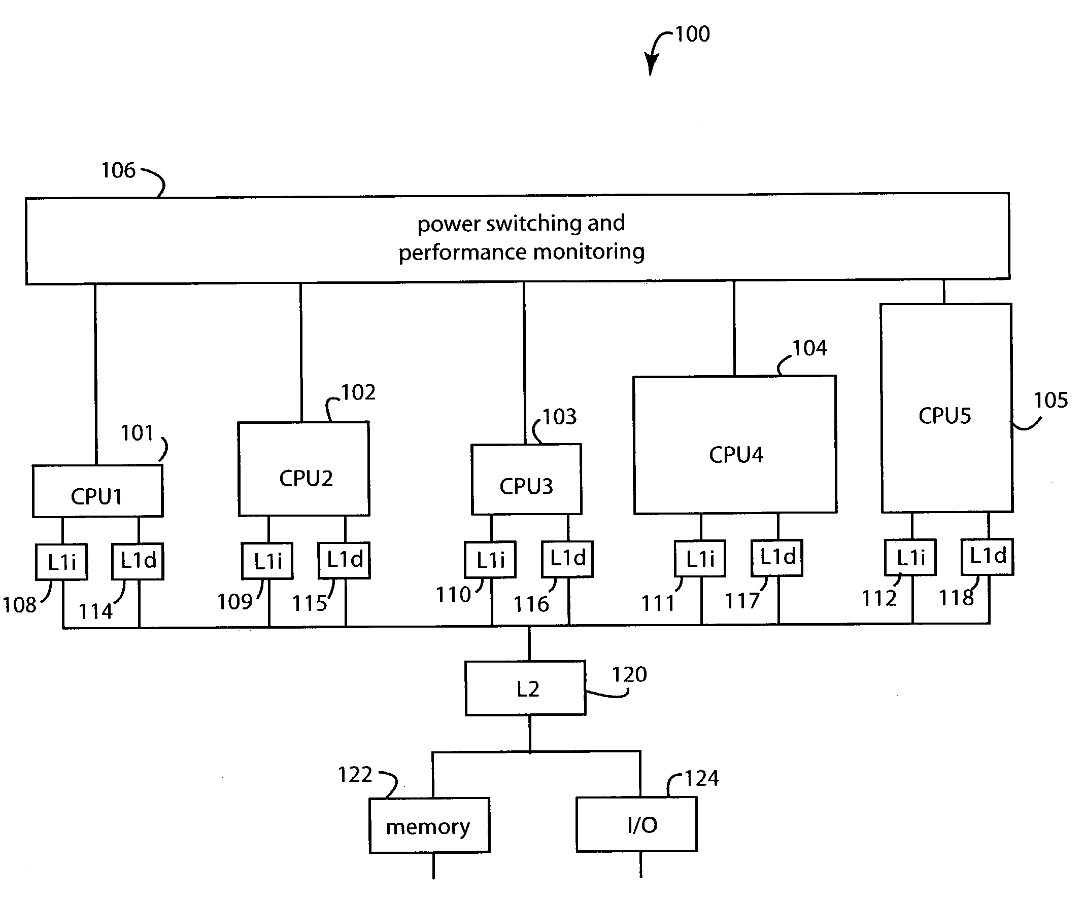
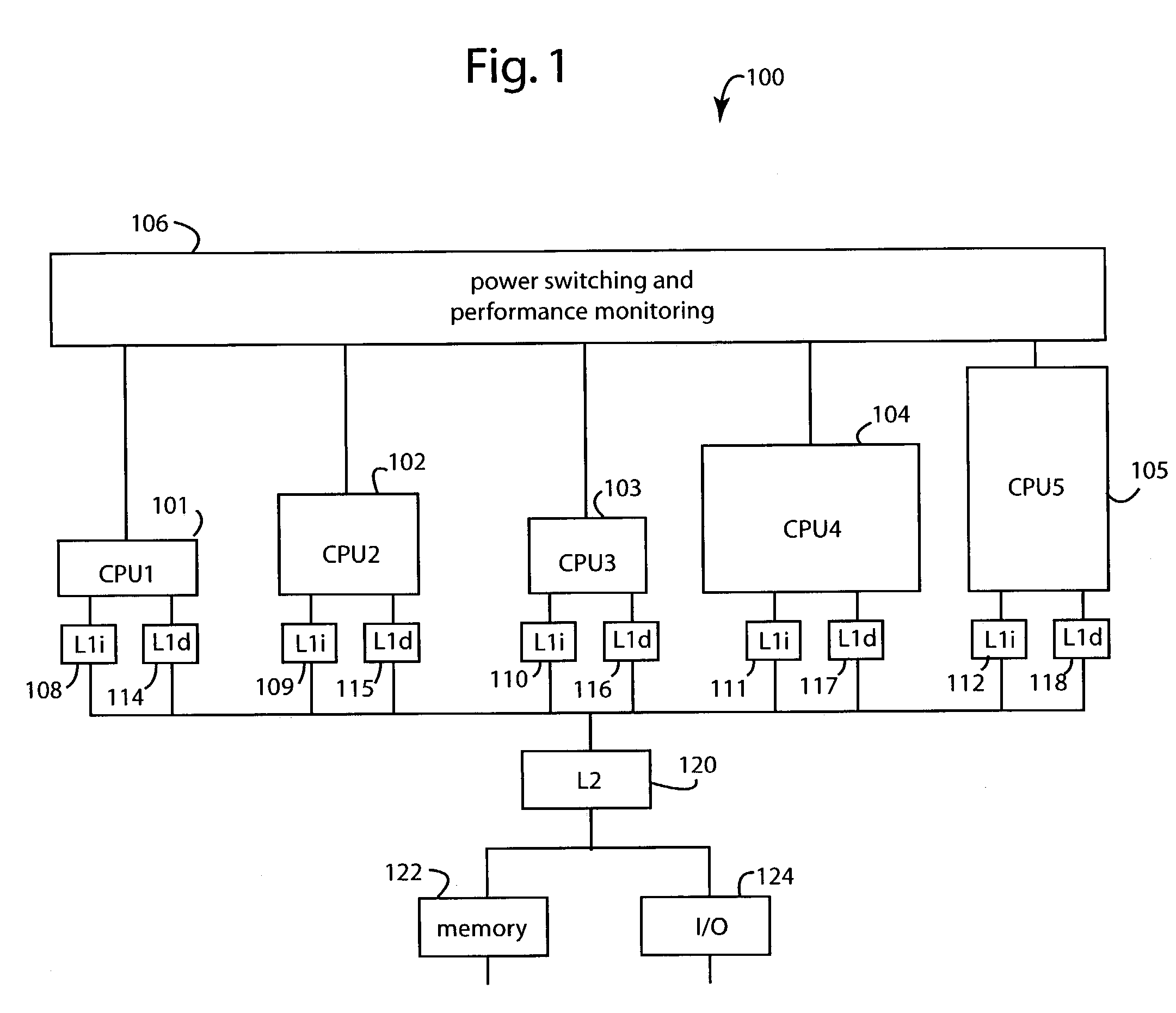
[0016]FIG. 1 illustrates a multi-core processor system embodiment of the present invention, and is referred to herein by the general reference numeral 100. Multi-core processor system 100 is a heterogeneous multi-core and core-switching implementation in a chip-level multi-core processor (CMP) with multiple, diverse processor cores that all execute the same instruction set. Each processor core includes significantly different resources and demonstrates significantly different performance and energy efficiency levels for the same application software. The operating system software tries to match the applications to the different cores during an application's execution to make the best use of the available hardware while maximizing energy efficiency at a given minimum performance level.

[0017]The system 100 hosts an operating system and application software that can execute single-threaded or multi-threaded. The operating system dispatches processing jobs to individual processor cores ...


PUM


Abstract

A computer system for conserving operating power includes a number of computer hardware processor cores that differ amongst themselves in at least in their respective operating power requirements and processing capabilities. A monitor gathers performance metric information from each of the computer hardware processor cores that is specific to a particular run of application software then executing. A workload transfer mechanism transfers the executing application software to a second computer hardware processor core in a search for reduced operating power. A transfer delay mechanism is connected to delay a subsequent transfer of the executing application software if the system operating power may be conserved by such delay.

Description

FIELD OF THE INVENTION[0001]The present invention relates to computer systems, and more specifically to methods and devices for reducing power use by dispatching processing jobs to the more energy-efficient processor core, in a pool of different-capability processor cores, that nevertheless provides acceptable performance.BACKGROUND OF THE INVENTION[0002]Computer software application programs do not always require the high-capability computing hardware resources that are at their disposal. But if some critical code passage or whole application program must run at maximum efficiency, conventional systems dedicate the necessary computing hardware full time. In a few prior art multiprocessor systems that run applications that can be split and paralleled, pools of identical processor cores can be added in sufficient numbers to get the job done.[0003]Some waste can be involved in the mismatching of software with modest resource requirements on high performance hardware platforms. When th...

Claims


Application Information

Patent Timeline
Patent Type & Authority Patents(United States)
IPC IPC(8): G06F1/32
CPCG06F1/3203G06F1/329G06F1/3293G06F9/5088Y02B60/162Y02B60/121Y02B60/144Y02D10/00
Inventor FARKAS, KEITHJOUPPI, NORMAN P.MAYO, ROBERT N.RANGANATHAN, PARTHASARATHY
Owner HEWLETT PACKARD DEV CO LP
Why Eureka
Try Eureka