CATV trunk amplifier, upward signal amplifier, and bi-directional CATV system

a catv amplifier and trunk technology, applied in the field of catv amplifiers, can solve the problems of increasing the cn ratio (carrier-to-noise ratio) of reducing the power consumption of the entire catv amplifier, and reducing the accuracy of receiving the upward h signal on the center equipment side. the effect of improving the accuracy of receiving the upward h signal

Inactive Publication Date: 2006-08-15
MASPRODENKOH KK
View PDF9 Cites 4 Cited by
  • Summary
  • Abstract
  • Description
  • Claims
  • Application Information

AI Technical Summary

Benefits of technology

[0040]In this manner, it is possible to directly transmit the upward H signal, transmitted via the CATV amplifiers located closer to the terminal device side than the second CATV amplifier, to the center equipment via the optical transmission path. Thus, confluent noises transmitted to the center equipment, created on the transmission line by noise in the transmission frequency band of the upward H signal generated on the terminal device side, are reduced. The accuracy of receiving the upward H signal on the center equipment side can then be improved.

Problems solved by technology

As a result, there is a problem in that the transmission losses of the upward H signal in the conventional CATV amplifier increase twice as large as the transmission losses of the upward L signal, and the CN ratio (carrier-to-noise ratio) of the upward H signal is reduced.
Thus, there arises another problem in that the power consumption of the entire CATV amplifier is also increased.
Accordingly, the power consumption of the entire CATV amplifier is also caused to increase.
Furthermore, as the power consumption of the CATV amplifier is increased, distortion due to the hum modulation generated in the CATV amplifier grows larger.
Therefore, in a general bi-directional CATV system supplying power from a power unit to a plurality of CATV amplifiers via the transmission lines, there is another problem in that the distortion due to the hum modulation cannot be ignored.
Therefore, when the power consumption per CATV amplifier increases as above, the distortion due to the hum modulation generated in the entire system cannot be ignored.

Method used


Image

  • CATV trunk amplifier, upward signal amplifier, and bi-directional CATV system
  • CATV trunk amplifier, upward signal amplifier, and bi-directional CATV system
  • CATV trunk amplifier, upward signal amplifier, and bi-directional CATV system

Examples


Embodiment Construction

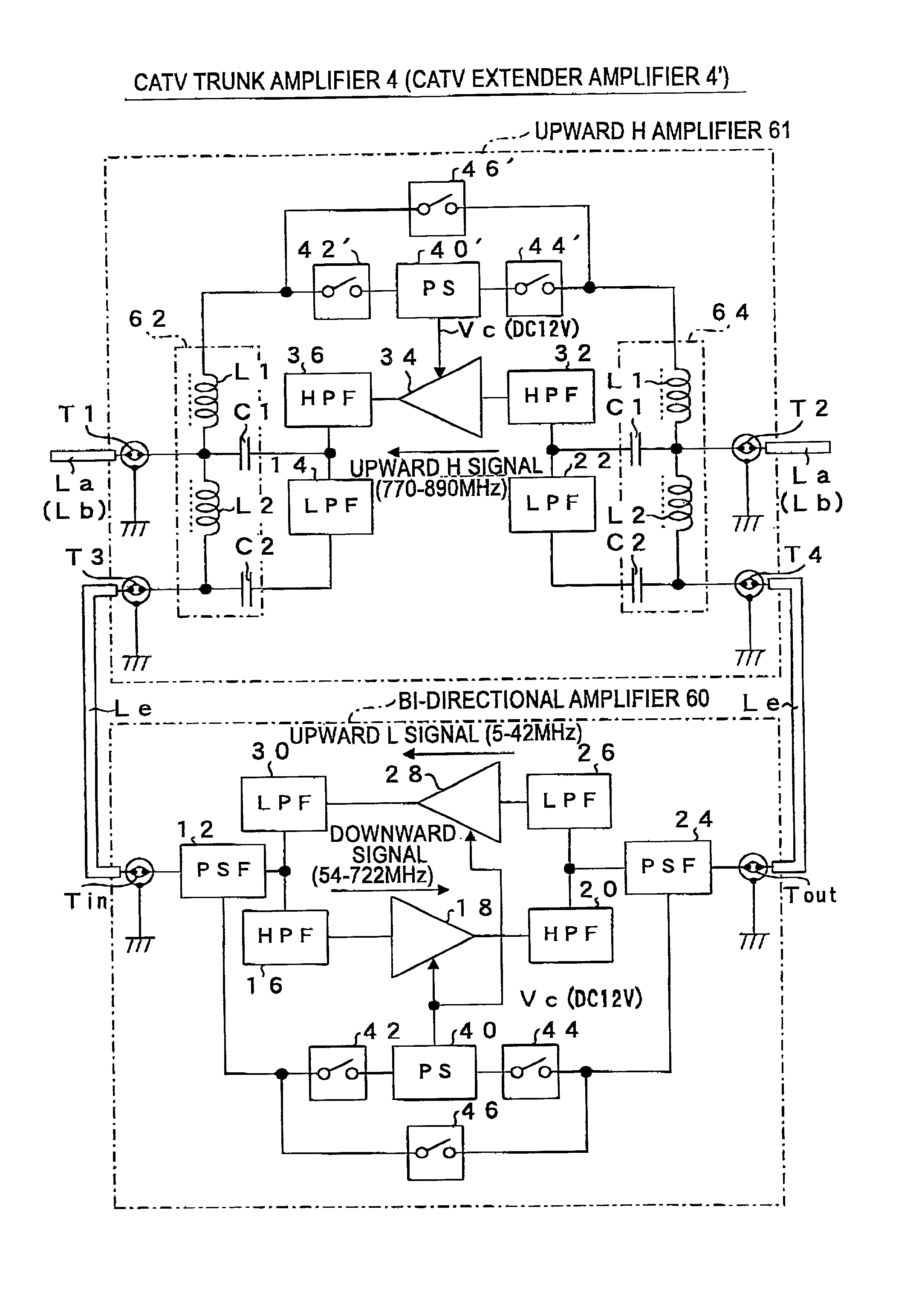
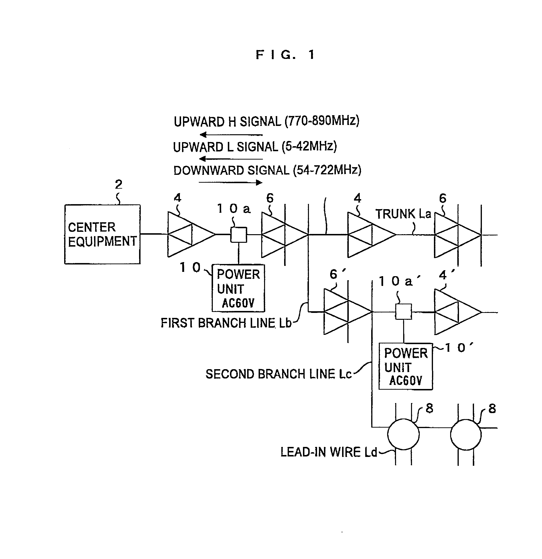
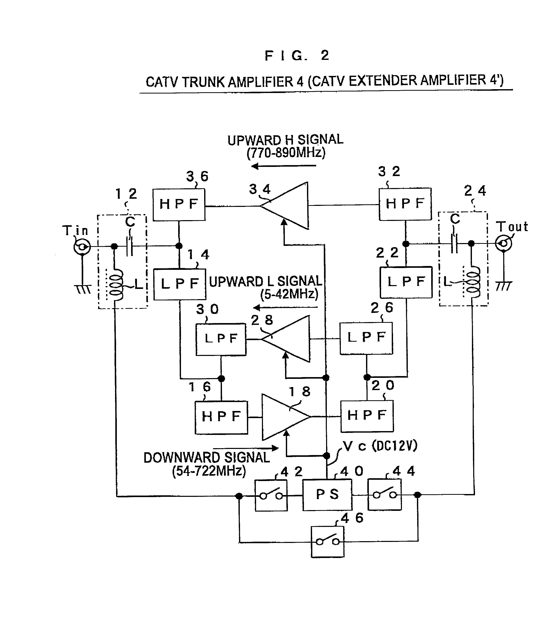
[0049]As shown in FIG. 1, a bi-directional CATV system of the present embodiment transmits a downward signal in a predetermined transmission frequency band (for example, ranging from 54 to 722 MHz) from the center equipment 2 to a terminal device. The bi-directional CATV system of the present embodiment also respectively transmits an upward L signal, in a transmission frequency band (for example, ranging from 5 to 42 MHz) lower than the frequency band of the downward signal, and an upward H signal, in a frequency band (for example, ranging from 770 to 890 MHz) higher than the frequency band of the downward signal, from the terminal device to the center equipment 2.

[0050]The bi-directional CATV system comprises, as transmission lines for bi-directionally transmitting the aforementioned signals between the center equipment 2 and the terminal devices on the side of subscribers of the CATV system, a trunk La connected to the center equipment 2. The system also comprises a plurality of f...


PUM


Abstract

In a CATV trunk amplifier, a downward signal input to an input terminal from the center equipment side is input to a downward amplifying circuit via a first filter and a second filter. The amplified downward signal is output to the terminal device side via the second filter, the first filter, and an output terminal. An upward L signal is input from the terminal device side via the output terminal to an upward L amplifying circuit via the first filter and a third filter. The amplified upward L signal is output to the center equipment side via the third filter, the first filter, and the input terminal. An upward H signal is input to an upward H amplifying circuit via a fourth filter. The amplified upward H signal is output to the center equipment side via the fourth filter and the input terminal.

Description

BACKGROUND OF THE INVENTION[0001]i) Technical Field of the Invention[0002]This invention relates to a CATV amplifier provided on a transmission line from the center equipment of a bi-directional CATV system to terminal devices, respectively amplifying upward signals and downward signals bi-directionally flowing through the transmission line.[0003]ii) Description of the Related Art[0004]Conventional CATV amplifiers are provided on a trunk connected to center equipment and branch lines, branching from the trunk, in a bi-directional CATV system. They amplify bi-directional signals flowing through the transmission lines. Such CATV amplifiers (specifically, CATV trunk amplifiers, CATV trunk bridger amplifiers, CATV extender amplifiers, and CATV bridger amplifiers provided on the branch lines branching from the trunk) comprise a downward amplifying circuit for amplifying a downward signal transmitted from the center equipment to the terminal devices, and an upward amplifying circuit for a...

Claims


Application Information

Patent Timeline
Patent Type & Authority Patents(United States)
IPC IPC(8): H04N7/173H04B3/36H04B3/58H04B7/14H04N7/16H04B3/38H04N5/00H04N7/10H04N21/437H04N21/647
CPCH04N7/102
Inventor SUGIURA, TOSHIHIROGOTO, HIRONORI
Owner MASPRODENKOH KK
Why Eureka
Try Eureka