

Lightning strike mitigation system
- Summary
- Abstract
- Description
- Claims
- Application Information
AI Technical Summary
Benefits of technology
Problems solved by technology
Method used
Image

Examples
first embodiment
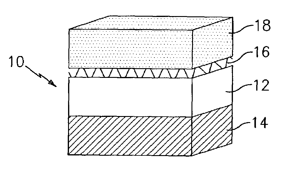
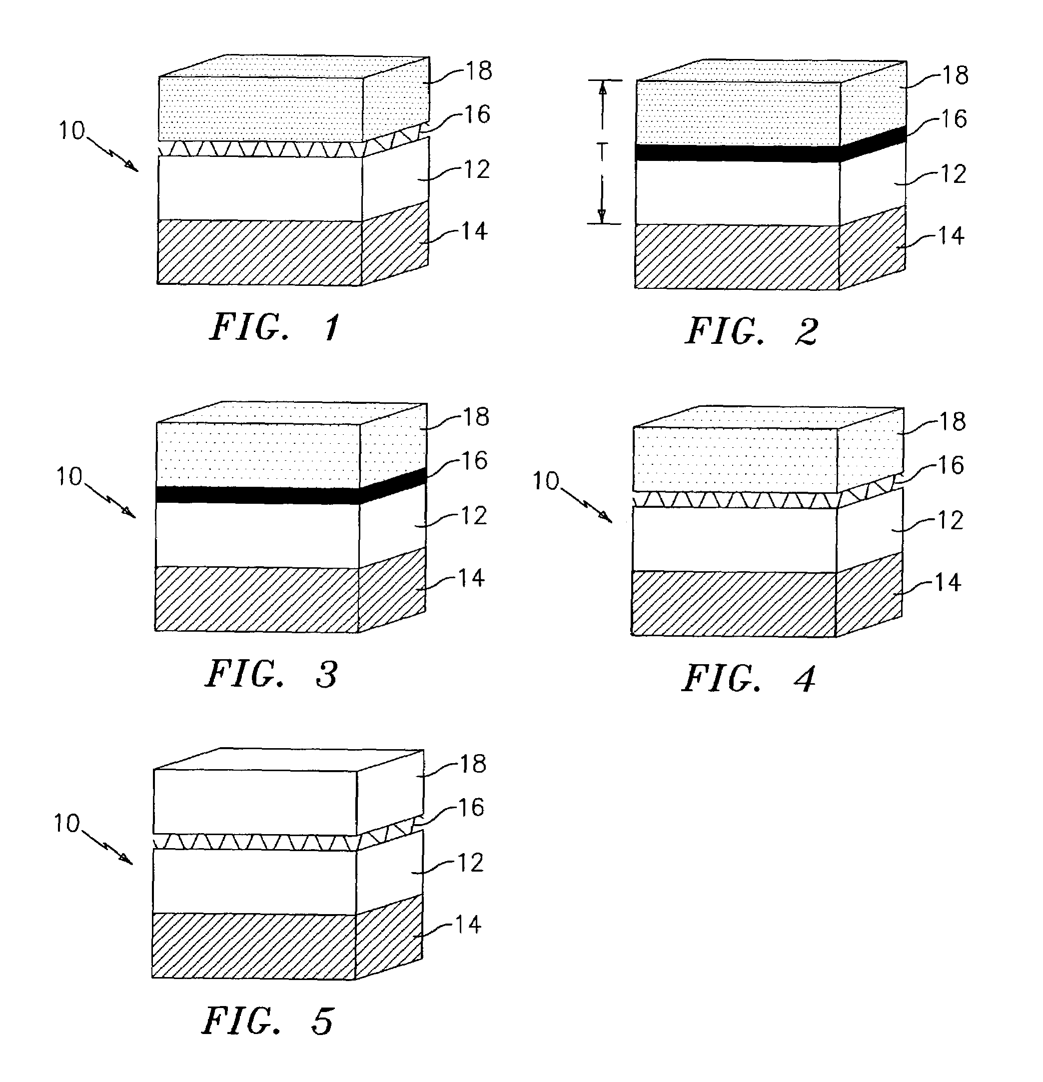
[0014]Referring now to FIG. 1, a lightning strike mitigation system 10 is illustrated. In this embodiment, a first layer 12 of ablative insulating material is formed adjacent the protected airframe surface 14 of a vehicle such as an aircraft, spacecraft, missile, or rocket. The protected airframe surface 14 may be formed from any suitable metallic, semi-metallic, or non-metallic material known in the art, e.g. a cured carbon epoxy material. The layer 12 is formed from an ablative insulator with no metal fill. The layer 12 has a thickness sufficient to insulate / protect the airframe surface for the entire service life assuming there are no protective layers intact above it. The thickness of layer 12 is determined by testing and analysis given the flight environment, speed, duration and service life margins of safety. An electrically conductive material 16, such as a copper or aluminum mesh, is placed on top of the ablative insulating layer 12. Mesh 0.10″ thick or less with 70–80% open...
third embodiment
[0016]FIG. 3 illustrates a lightning strike mitigation system 10. In this embodiment, the inner layer 12 is formed from an ablative insulating material with no metal fill, while the outer layer 18 is formed from an ablative insulating material with a 15% nickel fill. Layers 12 and 18 may be a multi-layer, non-homogeneous material of composite makeup. Materials components may include, but are not limited to, filled / unfilled R. E. Darling EP688, AST Sil-Cork, Cytek MXS 385, FMI Flexfram 605 TH, Dapco 2100 and 2900, Kirkhill Fastblock 301, 304 and 800, Lockheed Martin MA-25, custom-filled mixture utilizing base silicone used in Lockheed Martin MA-25, Aerotherm Acusil, filled / unfilled Electrolite ELC-325, filled Insulcast RTVS828 and Techno TSE-3331, filled / unfilled polyimide. The electrically conductive layer 16 is preferably formed from a copper, copper base alloy, aluminum, or aluminum-based alloy foil. The layer 16 may have any thickness with 0.0015″–0.008″ preferred nominal. Pure A...
fourth embodiment
[0017]FIG. 4 illustrates a lightning strike mitigation system 10 wherein the inner and outer layers 12 and 18 are formed from the same materials as in the embodiment of FIG. 3. In this embodiment, the electrically conductive layer 16 is formed from a copper or aluminum mesh material.
[0018]FIG. 5 illustrates yet another embodiment of a lightning strike mitigation system 10 in accordance with the present invention. In this embodiment, the inner and outer layers 12 and 18 are each formed from an ablative insulating material with no metal fill and the electrically conductive layer 16 is formed from a copper or aluminum mesh.
[0019]The electrically conductive material layer 16 is preferably located at or near the mid-point of the overall thickness T of the lightning strike mitigation system 10.
[0020]The finished product has the ablative insulation material sprayed onto a final bond surface, protected airframe surface or onto a releasable contoured mold surface. The system is installed by ...
PUM
| Property | Measurement | Unit |
|---|---|---|
| temperature | aaaaa | aaaaa |
| surface temperatures | aaaaa | aaaaa |
| electrically conductive | aaaaa | aaaaa |
Abstract
Description
Claims
Application Information