Floating piston for augmenting pressurized fluid flow during vehicle braking operations

a technology of pressurized fluid and floating piston, which is applied in the direction of braking system, braking components, transportation and packaging, etc., can solve the problems of vehicle wheels losing traction and spinning, and achieve the effect of effective augmenting the pressurized fluid and improving the response ra

Active Publication Date: 2006-08-22
KELSEY HAYES CO
View PDF6 Cites 22 Cited by
  • Summary
  • Abstract
  • Description
  • Claims
  • Application Information

AI Technical Summary

Benefits of technology

[0010]A connecting conduit connects the first braking circuit and the second braking circuit. The connecting conduit has a piston assembly disposed therein, which includes a cylindrical housing with a floating piston disposed within the cylindrical housing. The floating piston is adapted to be displaced by the pressurized fluid provided by the first source of pressurized fluid when the first hydraulic conduit of the first braking circuit is closed. The displacement of the floating piston subsequently generates an additional volume of pressurized fluid in the second hydraulic conduit of the second braking circuit. The additional volume of pressurized fluid in the second hydraulic conduit effectively augments the pressurized fluid provided by the second source of pressurized fluid in the second braking circuit, improving the response rate in achieving a desired braking pressure at the second wheel brake.

Problems solved by technology

During vehicle acceleration, a vehicle wheel may lose traction, and begin to spin.

Method used


Image

  • Floating piston for augmenting pressurized fluid flow during vehicle braking operations
  • Floating piston for augmenting pressurized fluid flow during vehicle braking operations
  • Floating piston for augmenting pressurized fluid flow during vehicle braking operations

Examples


Embodiment Construction

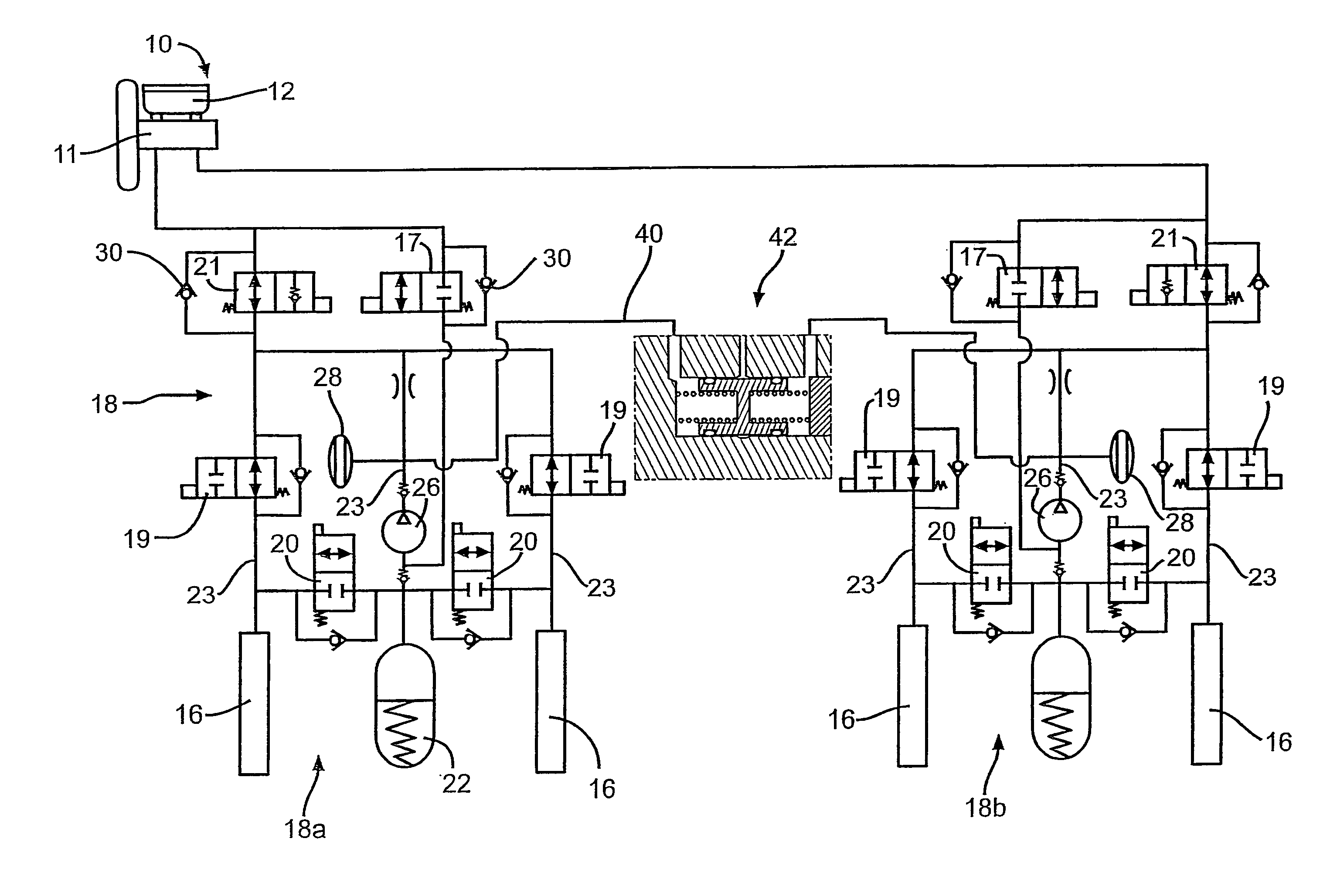
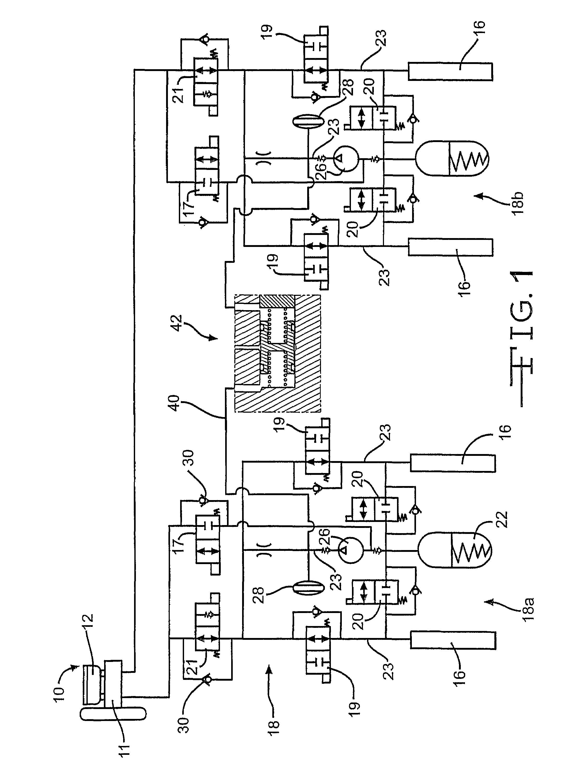
[0017]Referring now to the drawings, there is illustrated in FIG. 1 a vehicular brake system, indicated generally at 10, incorporating the floating piston of the present invention. System 10 includes valves and other components described below to provide traction control and vehicle stability control functions. Although this invention will be described in the context of the illustrated braking system 10, it will be appreciated that the floating piston of this invention may be integrated into a variety of braking systems having configurations other than that illustrated and described herein. Examples of such alternate systems include, but are not limited to, electronic brake management systems or electro-hydraulic braking (EHB) systems.

[0018]The brake system 10 includes a brake pedal (not shown) connected to a master cylinder 11, having a fluid reservoir 12, for providing pressurized brake fluid to a plurality of wheel brakes 16. The wheel brakes 16 may be of any suitable type found ...


PUM


Abstract

A hydraulic braking system including first and second braking circuits. The first and second braking circuits each include a wheel brake, a pressurized fluid source, and a hydraulic conduit connecting the wheel brake to the fluid source. Each of the hydraulic conduits includes a control valve that operates to selectively prevent fluid flow from the pressurized fluid source to the wheel brake. A connecting conduit connects the first and second braking circuits. A floating piston is disposed within the connecting conduit and is adapted to be displaced by the pressurized fluid provided by the pressurized fluid source in the first braking circuit when the control valve of the first braking circuit is closed. The displacement of the piston generates an additional volume of pressurized fluid in the hydraulic conduit of the second braking circuit that effectively augments the pressurized fluid provided by the second pressurized fluid source.

Description

TECHNICAL FIELD OF THE INVENTION[0001]This invention relates in general to a vehicle braking system. In particular, this invention relates to a hydraulic braking system that integrates a floating piston into the system that operates to augment the pressurized fluid supplied to individual wheel brakes during vehicle braking operations.BACKGROUND OF THE INVENTION[0002]The ability to independently control the braking force at each of the vehicle's wheels enables operation of a vehicle brake system in various special modes of operation. One of these special modes of operation is traction control. During vehicle acceleration, a vehicle wheel may lose traction, and begin to spin. In the traction control mode of braking, the brake system is electronically actuated, without the driver stepping on the vehicle brake pedal, to individually brake the spinning wheel. When the wheel has slowed sufficiently to regain traction, the brake is released.[0003]Another of these special modes of operation...

Claims


Application Information

Patent Timeline
Patent Type & Authority Patents(United States)
IPC IPC(8): B60T8/34B60T13/00B60T17/04B60T17/22
CPCB60T17/221B60T17/04
Inventor HOOL, PATRICK H.RIZK, GAMIL M.
Owner KELSEY HAYES CO
Why Eureka
Try Eureka