Constant velocity universal joint

a constant velocity, universal joint technology, applied in the direction of rotary machine parts, couplings, mechanical equipment, etc., can solve the problem that the grinding process generally requires a relatively long machining time, and achieve the effect of improving the rotational balancing performance and minimizing the variation of the angle of conta

Inactive Publication Date: 2006-08-22
NTN CORP
View PDF22 Cites 13 Cited by
  • Summary
  • Abstract
  • Description
  • Claims
  • Application Information

AI Technical Summary

Benefits of technology

[0006]Accordingly, the present invention has for its object to provide an improved constant velocity universal joint wherein an spherical inner surface of an outer race and track grooves can be machined to exhibit a precision while the required machining time is reduced.
[0007]Another important object of the present invention is to enable a precision to be secured in the spherical inner surface of the inner race and the track grooves while the required machining time is reduced.
[0008]A further important object of the present invention is to minimize generation of heat resulting from contact of component parts, particularly minimization of the heat during an initial stage of use.

Problems solved by technology

The grinding process generally requires a relatively long machining time as compared with the cutting process.
Also, the grinding process requires the use of a coolant of a kind which is offensive to the environment.

Method used


Image

  • Constant velocity universal joint
  • Constant velocity universal joint
  • Constant velocity universal joint

Examples


Embodiment Construction

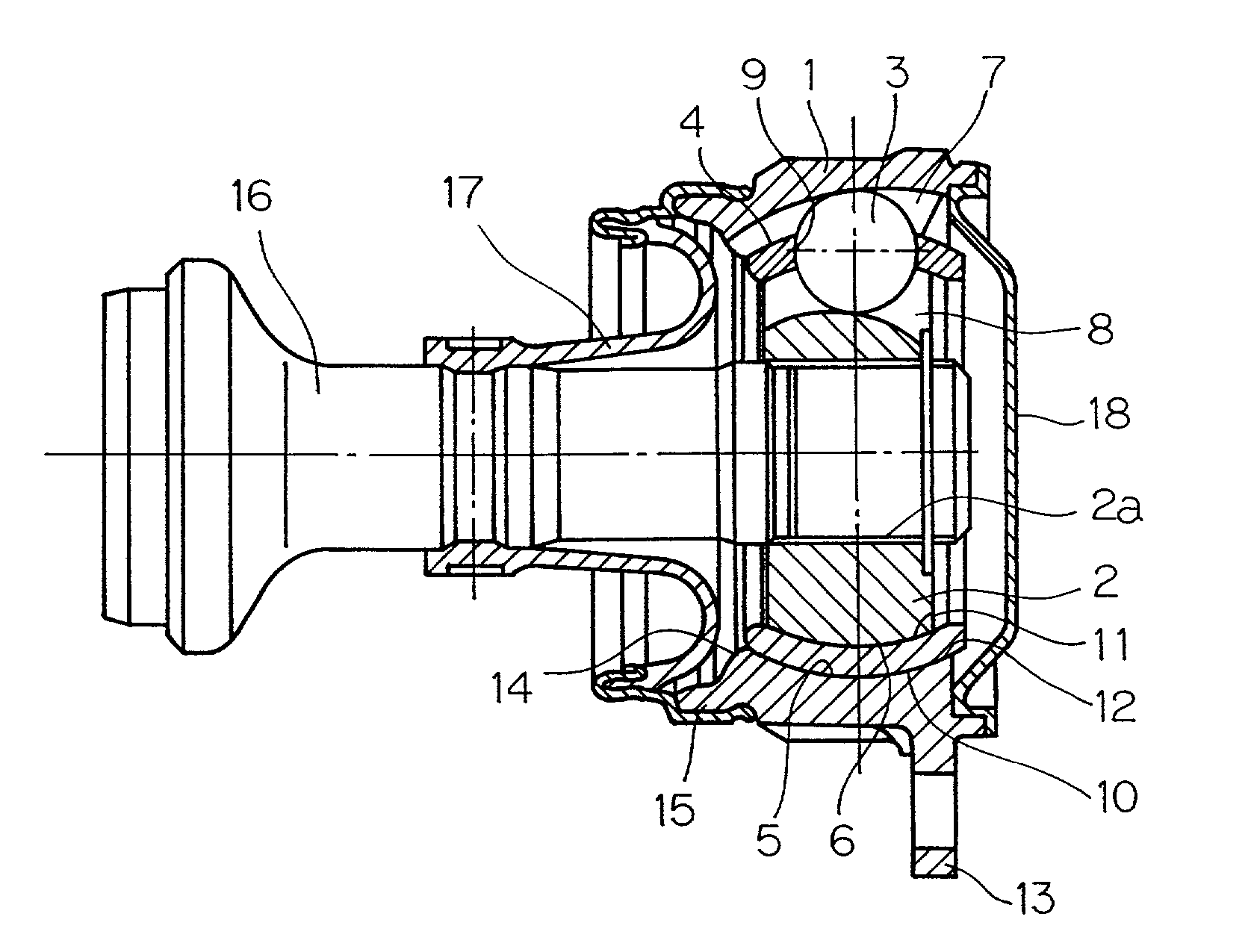
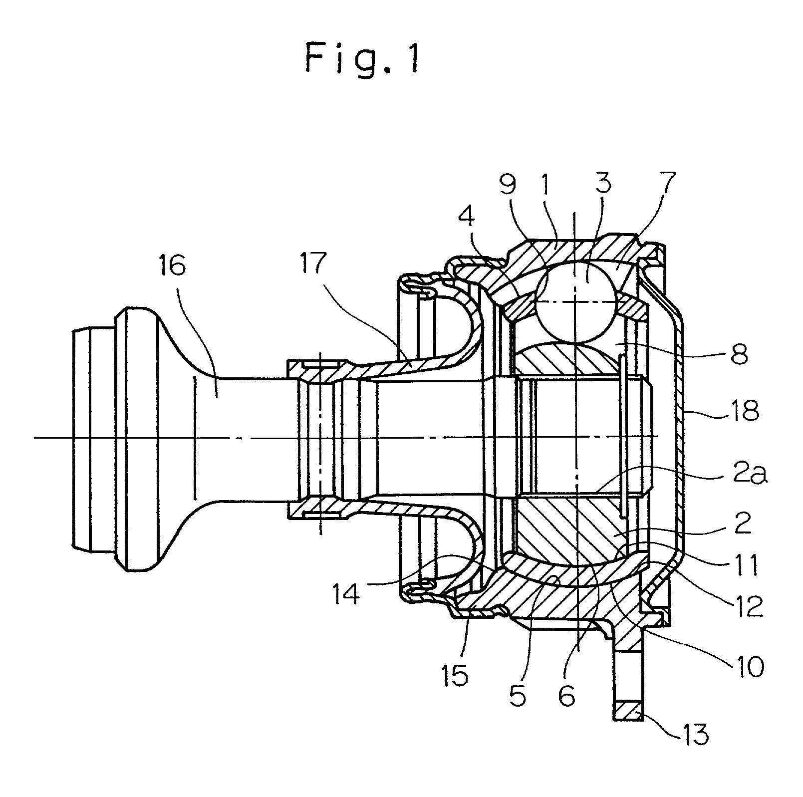
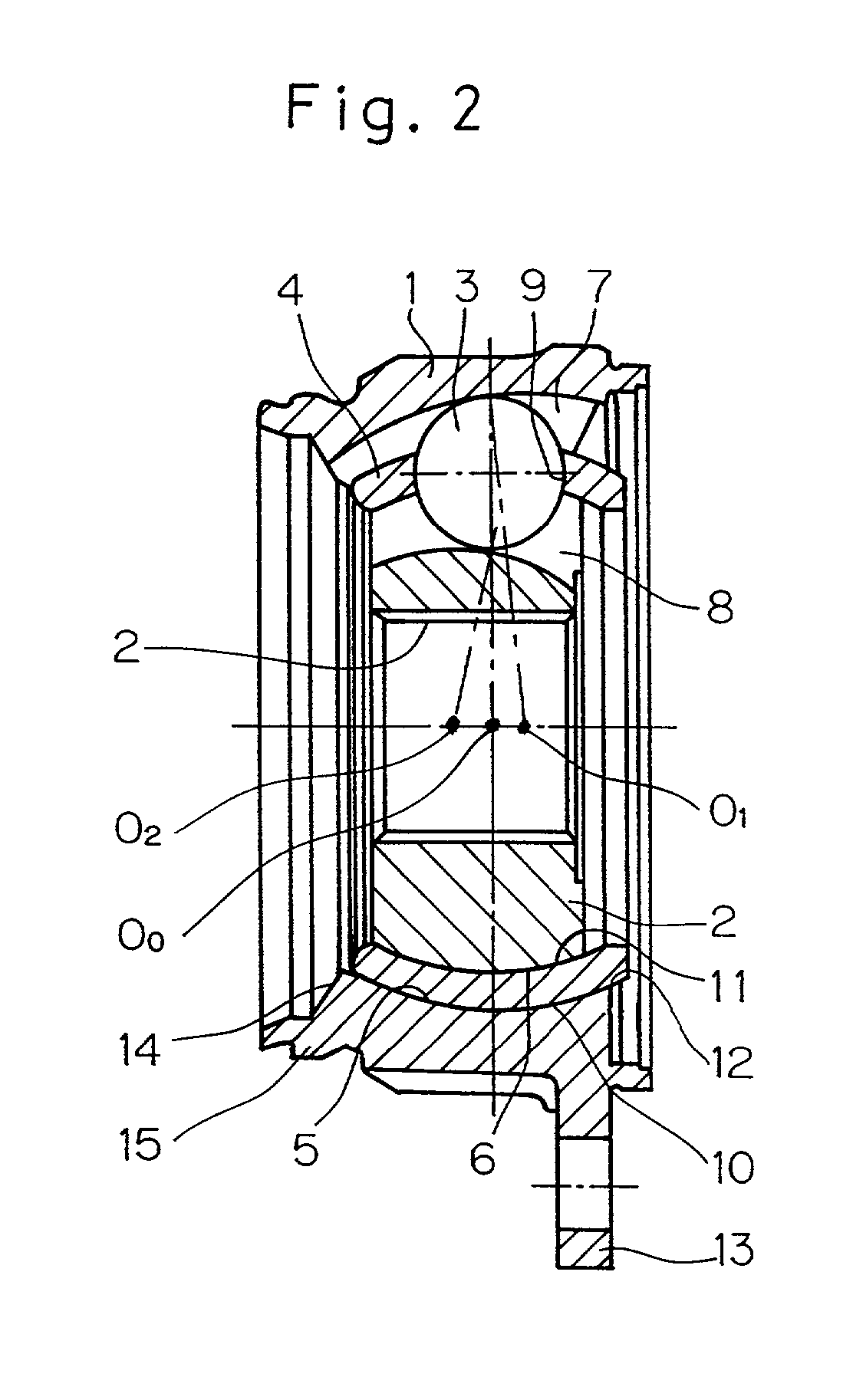
[0051]A preferred embodiment of the present invention will now be described with reference to the accompanying drawings. In describing the preferred embodiment, the present invention will be described as applied to a constant velocity universal joint of a fixed type for use on a propeller shaft. Referring particularly to FIG. 1, the illustrated constant velocity universal joint includes an outer race 1 having a spherical inner surface 5 formed with a plurality of axially extending track grooves 7, and an inner race 2 having a spherical outer surface 6 formed with a corresponding number of track grooves 8 cooperable with the track grooves 7 in the outer race 1. Torque transmitting balls 3 operatively retained by a retainer or cage 4 are interposed between the inner and outer races 2 and 1 with each ball 3 movably received in part in the respective groove 7 and in part in the mating groove 8. The retainer 4 has pockets 9 defined therein in a number equal to the number of the balls 3 u...


PUM


Abstract

A spherical inner surface of the outer race and track grooves in the outer race are each defined by a post-hardening cut surface. A spherical outer surface of the inner race and track grooves in the inner race are also each defined by a post-hardening cut surface. A retainer has a spherical outer surface, a spherical inner surface and inner surfaces of the pockets, all of which are defined by a post-hardening cut surface. Respective surfaces of the retainer, the outer race and the inner race which contact with each other are formed with a surface treatment layer for reducing a frictional resistance.

Description

BACKGROUND OF THE INVENTION[0001]1. Field of the Invention[0002]The present invention relates generally to a constant velocity universal joint for automotive vehicles and, more particularly, to the constant velocity universal joint used in an automobile propeller shaft.[0003]2. Description of the Prior Art[0004]The constant velocity universal joint for automotive vehicles, particularly the constant velocity universal joint used on an automobile propeller shaft when in use rotates at a high speed and does therefore require a capability of rotating in a balanced state and, also, a capability of suppressing internal heat generation. To attain a good rotatory balance, a gap present inside the universal joint has to be minimized in size. However, the smaller the gap, the more considerable generation of heat, and therefore in order to suppress the heat generation, the frictional resistance occurring between mating component parts must be reduced by minimizing surface roughness of those co...

Claims


Application Information

Patent Timeline
Patent Type & Authority Patents(United States)
IPC IPC(8): F16D3/224F16C19/16F16C33/38F16C33/44F16C33/58F16C33/64F16C33/66F16D3/2245
CPCF16C33/445F16D3/223F16D3/2245Y10S464/906F16D2003/22309F16D2250/00F16D2300/10F16D2003/22303
Inventor HOSOYA, TAKASHINAGASAWA, KEIZOIKEI, KATSUYUKI
Owner NTN CORP
Why Eureka
Try Eureka