Laser welding heat treat process

Inactive Publication Date: 2006-08-22
HONEYWELL INT INC
View PDF33 Cites 25 Cited by
  • Summary
  • Abstract
  • Description
  • Claims
  • Application Information

AI Technical Summary

Benefits of technology

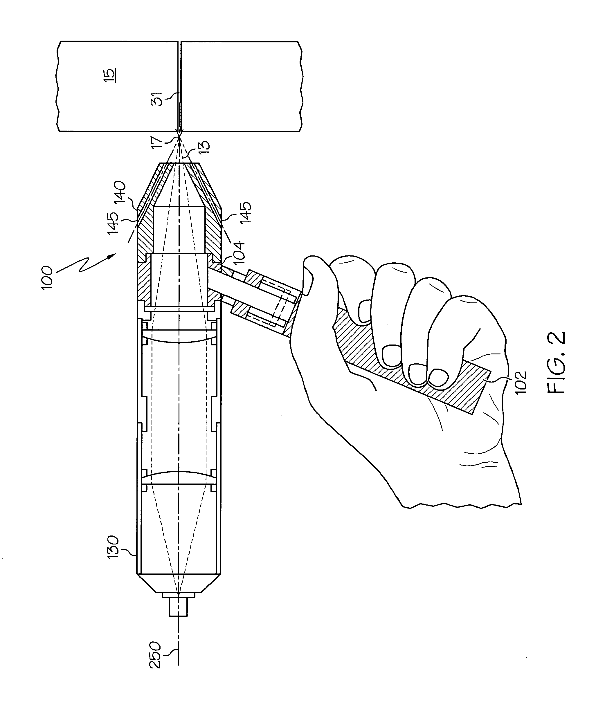
[0008]The present invention provides a method for repairing gas turbine engine components comprising superalloy materials. In one embodiment, and by way of example only, there is provided a method for providing a pre-welding heat treatment to a workpiece surface comprising the steps of: generating through a laser generator a laser beam characterized by a power and focal point; positioning the laser generator such that the focal point of the laser beam is above the workpiece surface so as to generate a defocused laser beam; directing the defocused laser beam toward the workpiece surface so as to project a laser beam spot on the workpiece surface; scanning the laser beam spot over the workpiece surface thereby heating the workpiece surface so as to provide a pre-welding heat treatment; repositioning the laser generator such that the focal point of the laser beam is changed; and laser welding the workpiece with substantially the same power as in the generating step. The workpiece may further include a crack having an edge such the step of scanning the laser beam spot further comprises moving the laser beam spot along a weld crack on the surface of the workpiece such that a circumference of the la

Problems solved by technology

The harsh operating conditions of high temperature and pressure that are now frequently specified place increased demands on engine components and materials.
Disadvantageously, the superalloys generally are very difficult to weld successfully.
Traditional repair methods have proven less than satisfactory for superalloy materials.
During a high temperature welding for example, a superalloy component may experience severe heat stress and cracking, giving the component undesired properties for further engine service.
Heating a component in pre-welding and post-welding steps with known devices such as induction heaters, quartz lamps, and heating blank

Method used


Image

  • Laser welding heat treat process
  • Laser welding heat treat process
  • Laser welding heat treat process

Examples


Embodiment Construction

[0019]The following detailed description of the invention is merely exemplary in nature and is not intended to limit the invention or the application and uses of the invention. Furthermore, there is no intention to be bound by any theory presented in the preceding background of the invention or the following detailed description of the invention. Reference will now be made in detail to exemplary embodiments of the invention, examples of which are illustrated in the accompanying drawings. Wherever possible, the same reference numbers will be used throughout the drawings to refer to the same or like parts.

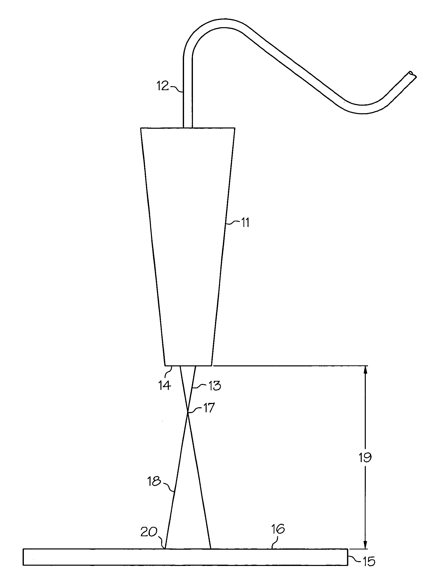
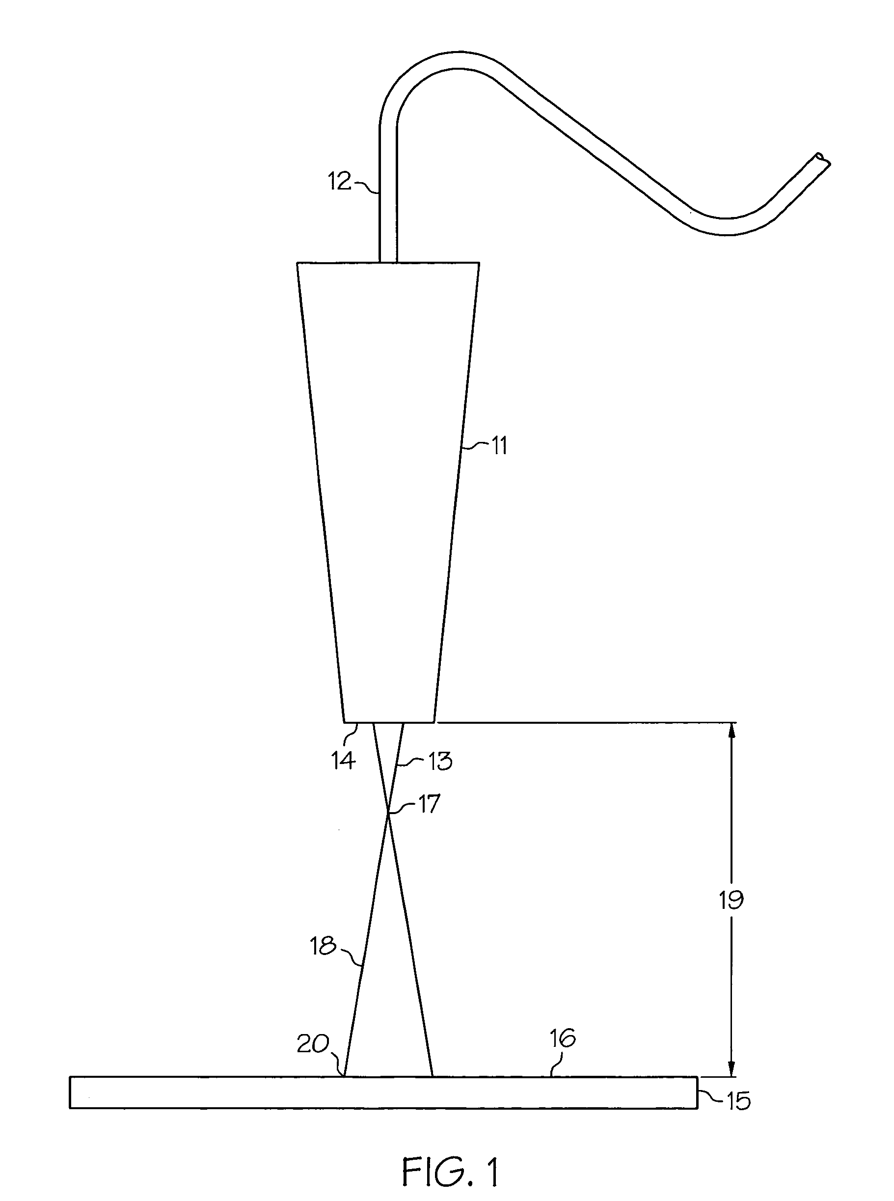
[0020]Referring now to FIG. 1 there is illustrated a laser torch 11 projecting a laser beam 13 that is useful for heat treating according to an embodiment of the present invention. The heat treating method utilizes a laser torch 11, preferably a hand held torch for use with laser powder fusion welding. As will be understood by those skilled in the art, laser torch 11 is represented i...


PUM

PropertyMeasurementUnit
Temperatureaaaaaaaaaa
Poweraaaaaaaaaa

Abstract

A method for providing a pre-welding heat treatment to a workpiece surface is described wherein the method includes the steps of: generating through a laser generator a laser beam characterized by a power and focal point; positioning the laser generator such that the focal point of the laser beam is above the workpiece surface so as to generate a defocused laser beam; directing the defocused laser beam toward the workpiece surface so as to project a laser beam spot on the workpiece surface; scanning the laser beam spot over the workpiece surface thereby heating the workpiece surface so as to provide a pre-welding heat treatment; repositioning the laser generator such that the focal point of the laser beam is changed; and laser welding the workpiece with substantially the same power as in the generating step. The method is further adapted for use with a hand held Nd:YAG laser torch, and the workpiece may be a superalloy gas turbine engine component.

Description

FIELD OF THE INVENTION[0001]The present invention relates to laser powder fusion welding of metallic materials. More particularly the invention relates to pre-welding and post-welding heat treatments to a superalloy workpiece using a hand-held laser welding torch.BACKGROUND OF THE INVENTION[0002]In an attempt to increase the efficiencies and performance of contemporary gas turbine engines, engineers have progressively pushed the engine environment to more extreme operating conditions. The harsh operating conditions of high temperature and pressure that are now frequently specified place increased demands on engine components and materials. Indeed the gradual improvement in engine design has come about in part due to the increased strength and durability of new materials that can withstand the operating conditions present in the modern gas turbine engines. With these changes in engine materials, there has arisen a corresponding need to develop new repair methods appropriate for such ...

Claims


Application Information

Patent Timeline
IPC IPC(8): B23K26/24
CPCB23K26/0096B23K26/1411B23P6/045B23P6/007B23K26/421B23K2201/001B23K26/144B23K26/60B23K2101/001
Inventor TAYLOR, CLYDE R.
Owner HONEYWELL INT INC
Why Eureka
Try Eureka