Lithographic apparatus, device manufacturing method and device manufactured thereby

a technology of lithographic apparatus and manufacturing method, which is applied in the direction of photomechanical apparatus, printers, instruments, etc., can solve the problems of irreversible reflection loss of optical elements, and achieve the effect of broad absorption spectrum and increased probability of optical elements being dislodged from the surfa

Active Publication Date: 2006-08-22
ASML NETHERLANDS BV
View PDF8 Cites 9 Cited by
  • Summary
  • Abstract
  • Description
  • Claims
  • Application Information

AI Technical Summary

Benefits of technology

[0021]The ability to subject only individual ones or subsets of the optical elements (i.e. not all of the optical elements) to cleaning ensures that the problem of overexposure can be reduced, because the cleanest optical elements in the system are avoided in the cleaning process. Thus, cleaning of the optical elements which require cleaning can be carried out while those optical elements that do not need cleaning are not cleaned.
[0053]The use of infra-red radiation is preferred because it is believed that such infra-red radiation causes an energy transition in the contaminant molecules (e.g. water) that are not caused in metal. The absorption of the infra-red photons by the contaminant molecules often causes the molecules to reach an excited state and thus increases the probability of their being dislodged from the surface. Water has a very broad absorption spectrum and so it is even possible with the present invention to dislodge only water molecules, while oxygen and hydrocarbon molecules are not affected. It is preferable, however, to also dislodge hydrocarbon molecules as well as water molecules.

Problems solved by technology

It has been discovered that overcleaning of the optical element can overexpose the optical element to light which can cause irreversible reflection loss of the optical element.

Method used


Image

  • Lithographic apparatus, device manufacturing method and device manufactured thereby
  • Lithographic apparatus, device manufacturing method and device manufactured thereby
  • Lithographic apparatus, device manufacturing method and device manufactured thereby

Examples


Embodiment Construction

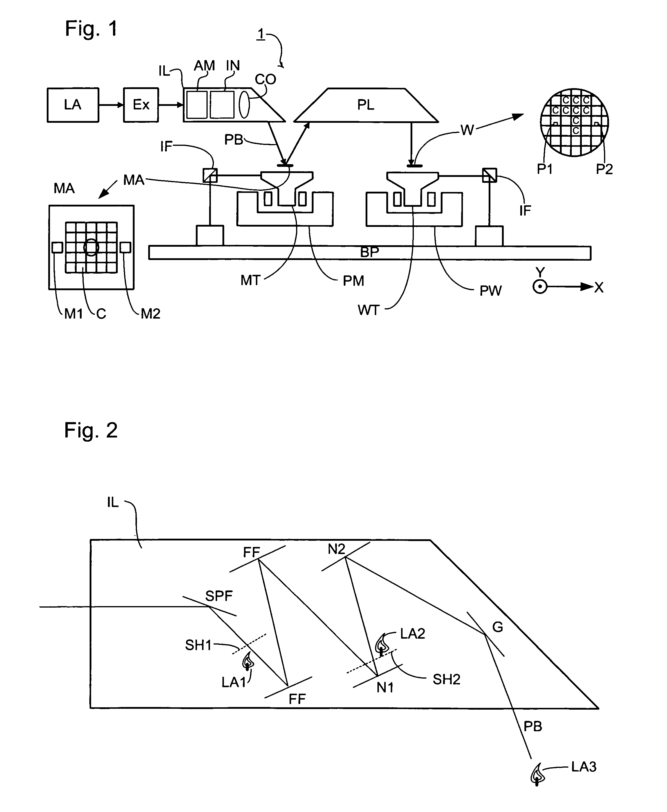
[0072]FIG. 1 schematically depicts a lithographic projection apparatus according to a particular embodiment of the invention. The apparatus comprises: a radiation system Ex, IL, for supplying a projection beam PB of radiation (e.g. EUV radiation), which in this particular case also comprises a radiation source LA; a first object table (mask table) MT provided with a mask holder for holding a mask MA (e.g. a reticle), and connected to a first positioning device for accurately positioning the mask with respect to item PL; a second object table (substrate table) WT provided with a substrate holder for holding a substrate W (e.g. a resist coated silicon wafer), and connected to a second positioning device for accurately positioning the substrate with respect to item PL; a projection system (“lens”) PL (e.g. a mirror group) for imaging an irradiated portion of the mask MA onto a target portion C (e.g. comprising one or more dies) of the substrate W. The term “object table” as used herein...


PUM

PropertyMeasurementUnit
wavelengthaaaaaaaaaa

Abstract

A lithographic projection apparatus is disclosed. The apparatus includes a radiation system that provides a beam of radiation, and a support structure that supports a patterning structure. The patterning structure is configured to pattern the beam of radiation according to a desired pattern. The apparatus also includes a substrate support that supports a substrate, a projection system that projects the patterned beam onto a target portion of the substrate, a plurality of optical elements that form part of at least one of the radiation system, the patterning structure, and the projection system; and a cleaning device. The cleaning device includes at least one cleaning beam of radiation, and a gas. The cleaning device is configured to clean an individual optical element or a subset of the plurality of optical elements.

Description

CROSS-REFERENCE TO RELATED APPLICATIONS[0001]This application is based on and claims the benefit of priority from European Patent Application No. 02258914.7 filed Dec. 20, 2002, the contents of which are incorporated herein by reference.BACKGROUND OF THE INVENTION[0002]1. Field of Invention[0003]The present invention relates generally to a lithographic projection apparatus. More specifically, the present invention relates to the cleaning of optical elements of a lithographic apparatus.[0004]2. Description of Related Art[0005]The term “patterning device” or “patterning structure” as here employed should be broadly interpreted as referring to a device or structure that can be used to endow an incoming radiation beam with a patterned cross-section, corresponding to a pattern that is to be created in a target portion of the substrate. The term “light valve” can also be used in this context. Generally, the said pattern will correspond to a particular functional layer in a device being cr...

Claims


Application Information

Patent Timeline
Patent Type & Authority Patents(United States)
IPC IPC(8): G03B27/52G03B27/42B08B7/00G03F7/20H01L21/027
CPCB08B7/0035G03F7/70925G03F7/20
Inventor STEVENS, LUCAS HENRICUS JOHANNESLEENDERS, MARTINUS HENDRIKUS ANTONIUSMEILING, HANSMOORS, JOHANNES HUBERTUS JOSEPHINA
Owner ASML NETHERLANDS BV
Why Eureka
Try Eureka