Optical time division multiplexing/demultiplexing system

a technology of optical time division and multiplexing, applied in multiplex communication, non-linear optics, instruments, etc., can solve the problems of constructive interference, time-consuming conversion, and major bottleneck in optical networks,

Inactive Publication Date: 2006-08-22
EVIDENT TECH
View PDF7 Cites 26 Cited by
  • Summary
  • Abstract
  • Description
  • Claims
  • Application Information

AI Technical Summary

Problems solved by technology

These conversions are time-consuming and a major bottleneck in optical networks.
Prior art OTDM implementations have encountered technological constraints that have prevented its implementation.
If the pulses are in phase, constructive interference occurs and the pulses can exit the device.
However, if the optical pulses are out of phase, deconstructive interference occurs and the optical signal cannot pass.
Optical loop type devices, such as disclosed in U.S. Pat. No. 5,493,433, are fairly fast (on the order of picoseconds) but are very power hungry and large.
Therefore, these devices requires extremely expensive components and are difficult to integrate into more complex systems because of their large size.
In addition, these types of devices are very sensitive to environmental factors such as temperature, because the refractive index of the fibers are related to temperature and because the length of fiber within the loop mirror is so long.
Therefore, a small temperature change greatly alters the performance of the device.

Method used


Image

  • Optical time division multiplexing/demultiplexing system
  • Optical time division multiplexing/demultiplexing system
  • Optical time division multiplexing/demultiplexing system

Examples


Embodiment Construction

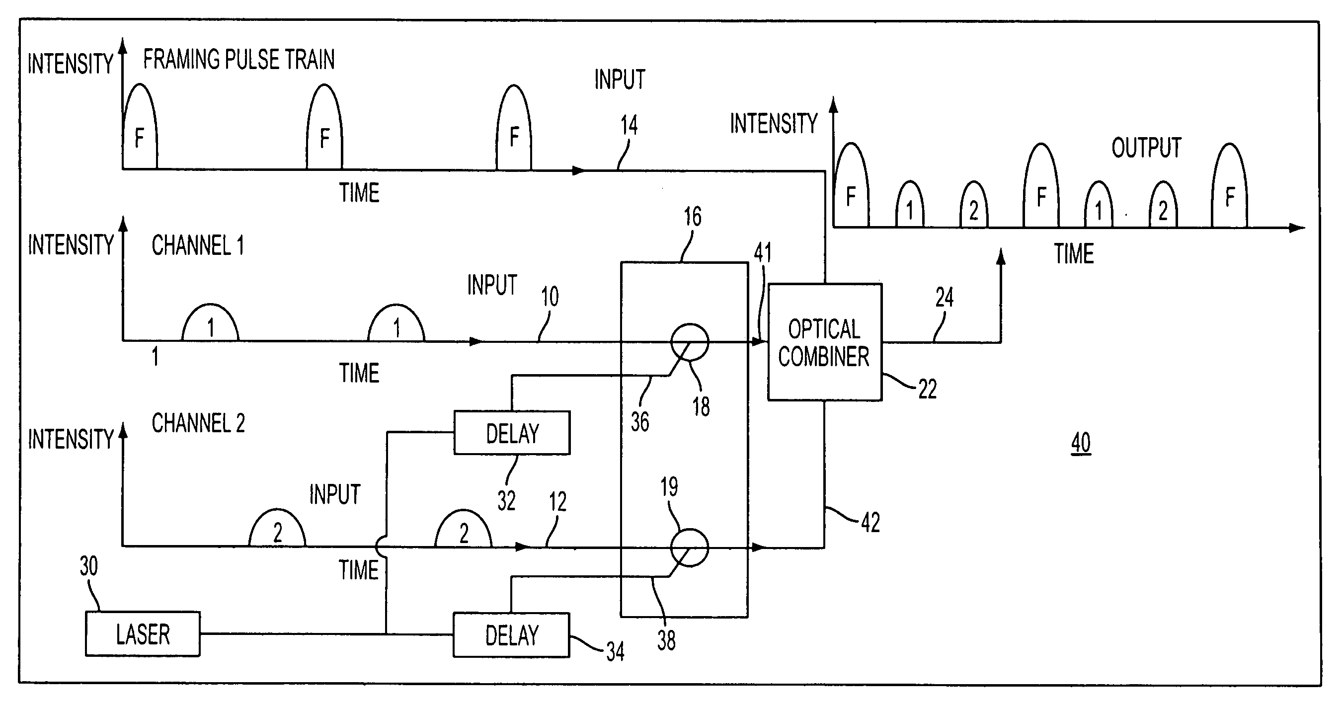
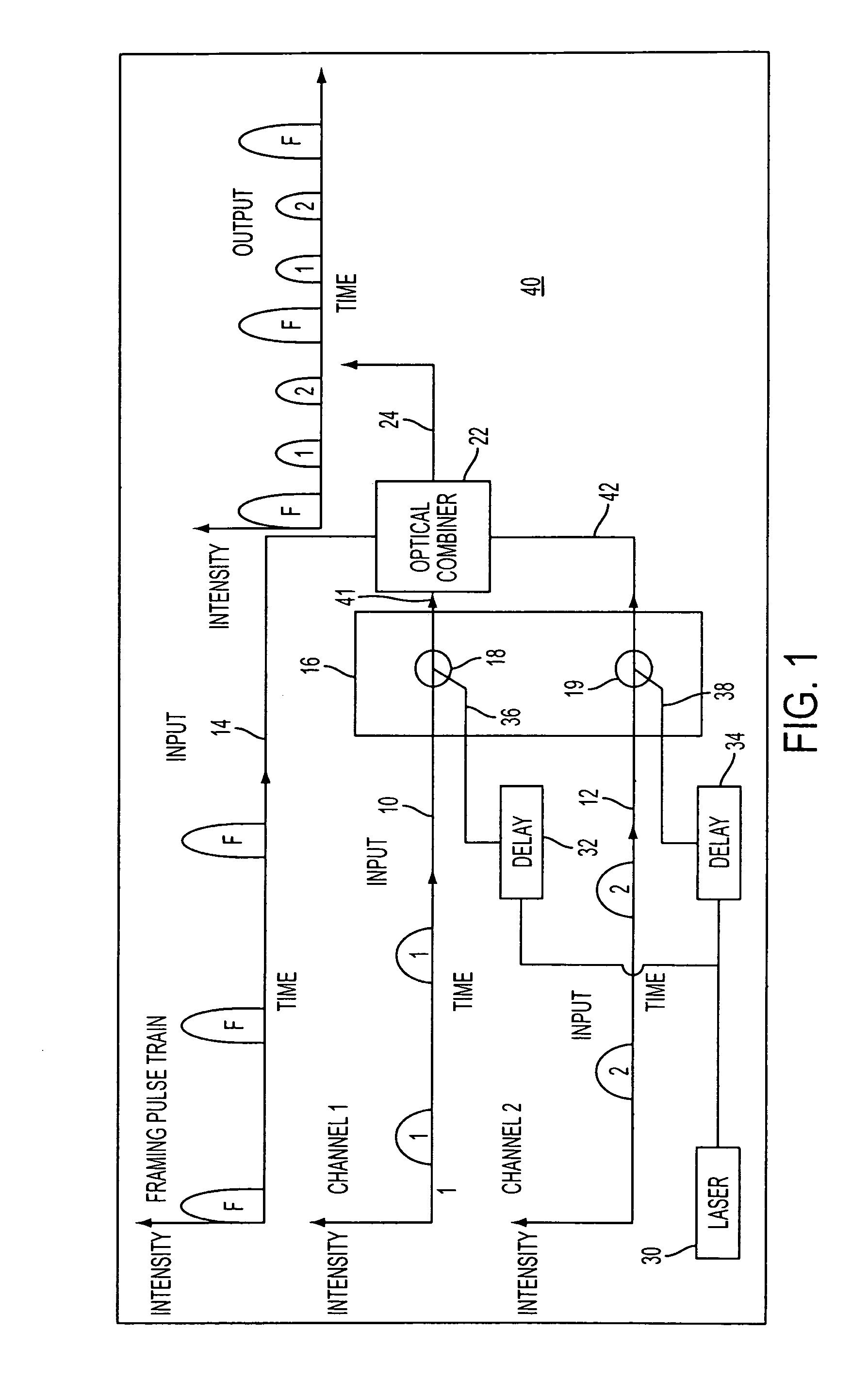
[0020]One embodiment of the present invention is an optical multiplexing / demultiplexing system that uses optical switches. The multiplexor combines or multiplexes lower data rate streams transmitted over independent optical fibers into a single, high data rate stream of data transmitted on a single optical fiber without converting the optical signal into an electrical form. The demultiplexor performs the opposite function.

[0021]FIG. 1 is a block diagram of a multiplexor portion of the system in accordance with one embodiment of the present invention. Multiplexor 40 includes N number of input signal optical fibers 10 and 12, an input framing optical fiber 14 that transmits high intensity (relative to the input signal pulses) framing pulses, and an array 16 of N all-optical switches 18 and 19. Input pulses on input fibers 10 and 12 are positioned in their corresponding TDM slot.

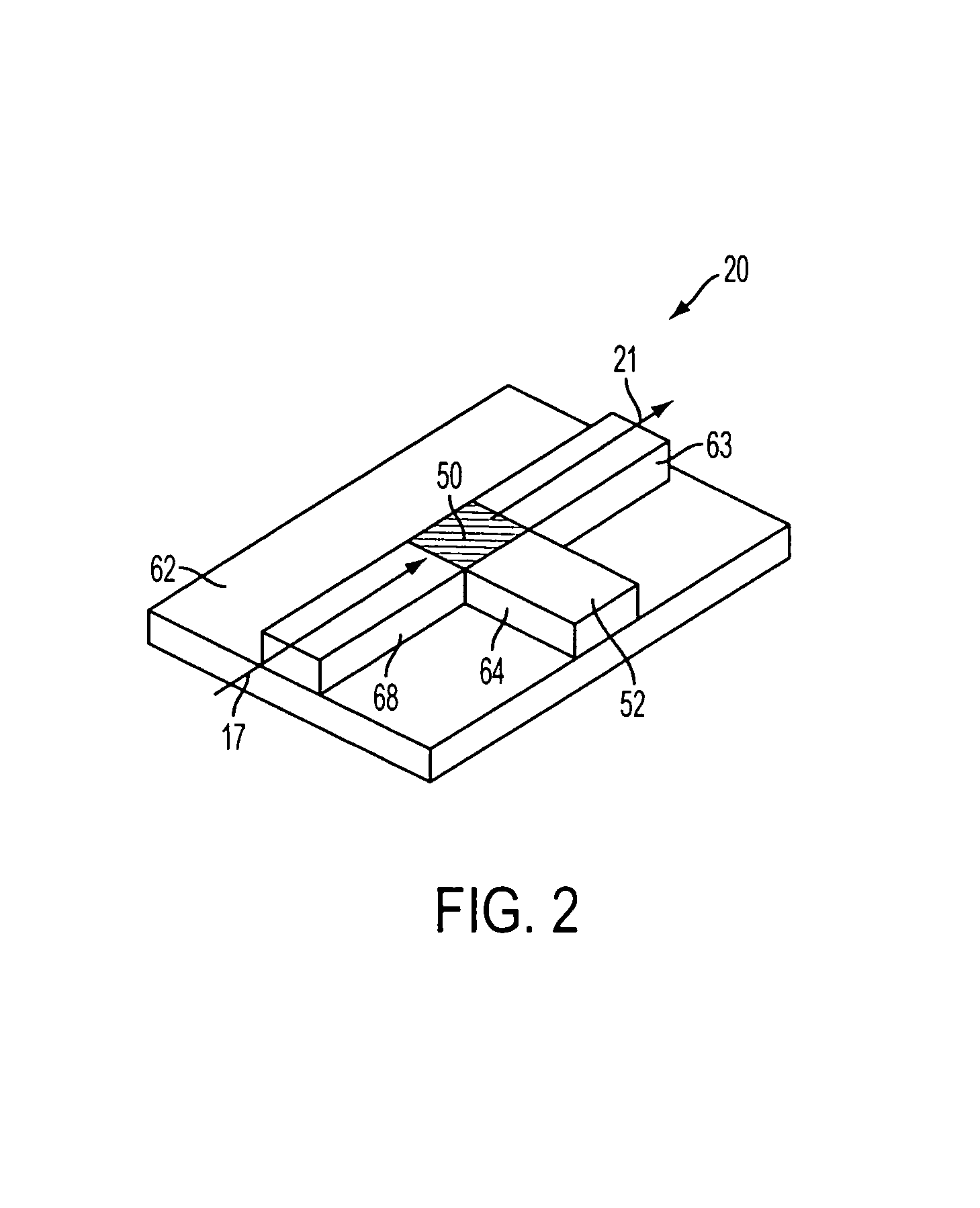
[0022]Array 16 of all-optical switches is used to truncate the optical data pulses of the different channels...


PUM

PropertyMeasurementUnit
diameteraaaaaaaaaa
thicknessaaaaaaaaaa
operational wavelengthaaaaaaaaaa

Abstract

A multiplexing/demultiplexing system has a multiplexor that includes a first plurality of optical switches having a plurality of outputs and a first plurality of optical delay elements coupled to the optical switches. A source of optical light is coupled to the delay elements, and an optical combiner is coupled to the plurality of outputs and a source of framing pulses. A demultiplexor includes a first and second splitter, and a threshold detector coupled to the first splitter. The demultiplexor further includes a second plurality of optical delay elements coupled to the threshold detector, and a second plurality of optical switches coupled to the second splitter and the second plurality of delay elements.

Description

CROSS-REFERENCES TO RELATED APPLICATIONS[0001]This application is related to U.S. patent application Ser. No. 09 / 737,470, filed Dec. 18, 2000 and entitled “Optical Switch Having A Saturable Absorber”.FIELD OF THE INVENTION[0002]The present invention is directed to optical communications. More particularly, the present invention is directed to an optical time division multiplexing / demultiplexing system.BACKGROUND INFORMATION[0003]Optical communication networks are rapidly being deployed to transmit both voice and data. Because the carrier frequencies used in optical fiber are orders of magnitude higher than used in any other communications medium, the bandwidth (i.e., data rate) afforded by such systems is inherently greater than twisted pair copper cables or coaxial cable.[0004]Nevertheless, the majority of optical networks use electronic devices for signaling because electronic routing and signal processing devices are well developed. In some cases, sophisticated protocols requirin...

Claims


Application Information

Patent Timeline
Patent Type & Authority Patents(United States)
IPC IPC(8): H04J14/08G02B6/35G02F1/017G02F1/35
CPCB82Y5/00H04J14/08G02F1/3515G02B6/355G02B6/356G02F1/3523G02F2001/01791G02F1/01791
Inventor LOCASCIO, MICHAELBALLINGER, CLINTON T.PRATT, CHESTER A.LANDRY, DANIEL P.
Owner EVIDENT TECH
Why Eureka
Try Eureka