
Modular robotic system and method for sample processing

a robotic system and module technology, applied in the field of automatic robotic systems, can solve the problems of reducing the rate of sample processing, affecting the adaptability of dedicated systems, and affecting the efficiency of sample processing,

Inactive Publication Date: 2006-08-22
THERMO CRS LTD
View PDF8 Cites 18 Cited by
  • Summary
  • Abstract
  • Description
  • Claims
  • Application Information

AI Technical Summary

Benefits of technology

"The present invention provides a method for processing objects using a bi-directional conveyance device with a plurality of instruments arranged at fixed intervals along the conveyance device and dedicated movers for loading and unloading of objects. The conveyance device operates in an interrupted motion to coordinate the loading and unloading of objects. The invention also provides an automated robotic system with a modular architecture consisting of a backbone, modules, and a bi-directional motion device for presenting objects adjacent to the module when connected to the backbone. The connection interface between the backbone and module provides a repeatable connection and disconnection capability for easy reconfiguration of the modular architecture."

Problems solved by technology

However, one disadvantage of these systems is that the sample throughput is rate-limited by the limited ability of the robot when required to feed multiple workstations.
However, these dedicated systems can be limited in their adaptability, for example, to new assay requirements.
It is common in the research environment that assay requirements change constantly, thereby making dedicated automation systems become either obsolete after the end of a campaign, or require extensive retooling to adjust to the new assay needs.
Nevertheless, in a chemical assay some steps may be repeated several times, meaning that in a sequential approach such devices have to be present in multiples, resulting in inefficient use of the process devices and unnecessarily high capital investment costs.
For example, automated robotic systems may contain third party equipment, such pipettors, incubators, readers and other third party equipment, which may not be built for a 24 hour operation and therefore be prone to failure.

Method used


Image

  • Modular robotic system and method for sample processing
  • Modular robotic system and method for sample processing
  • Modular robotic system and method for sample processing

Examples


Embodiment Construction

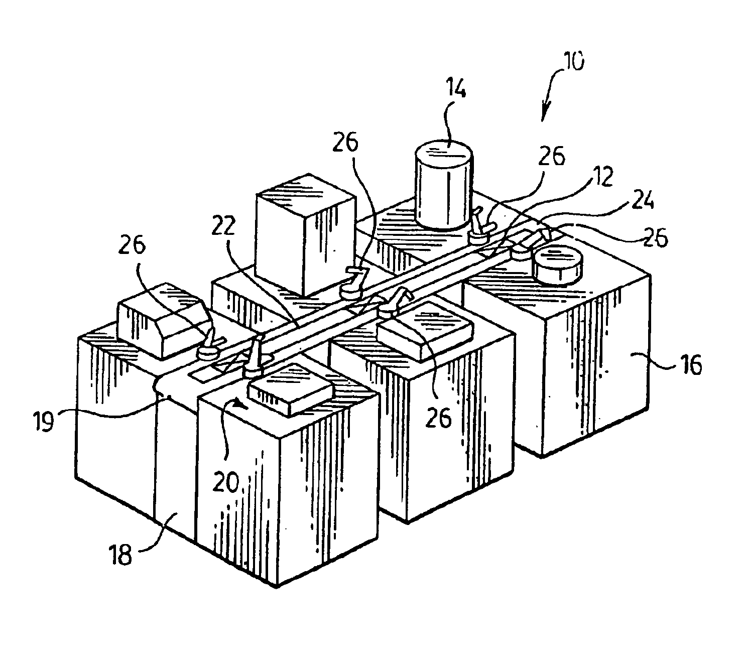
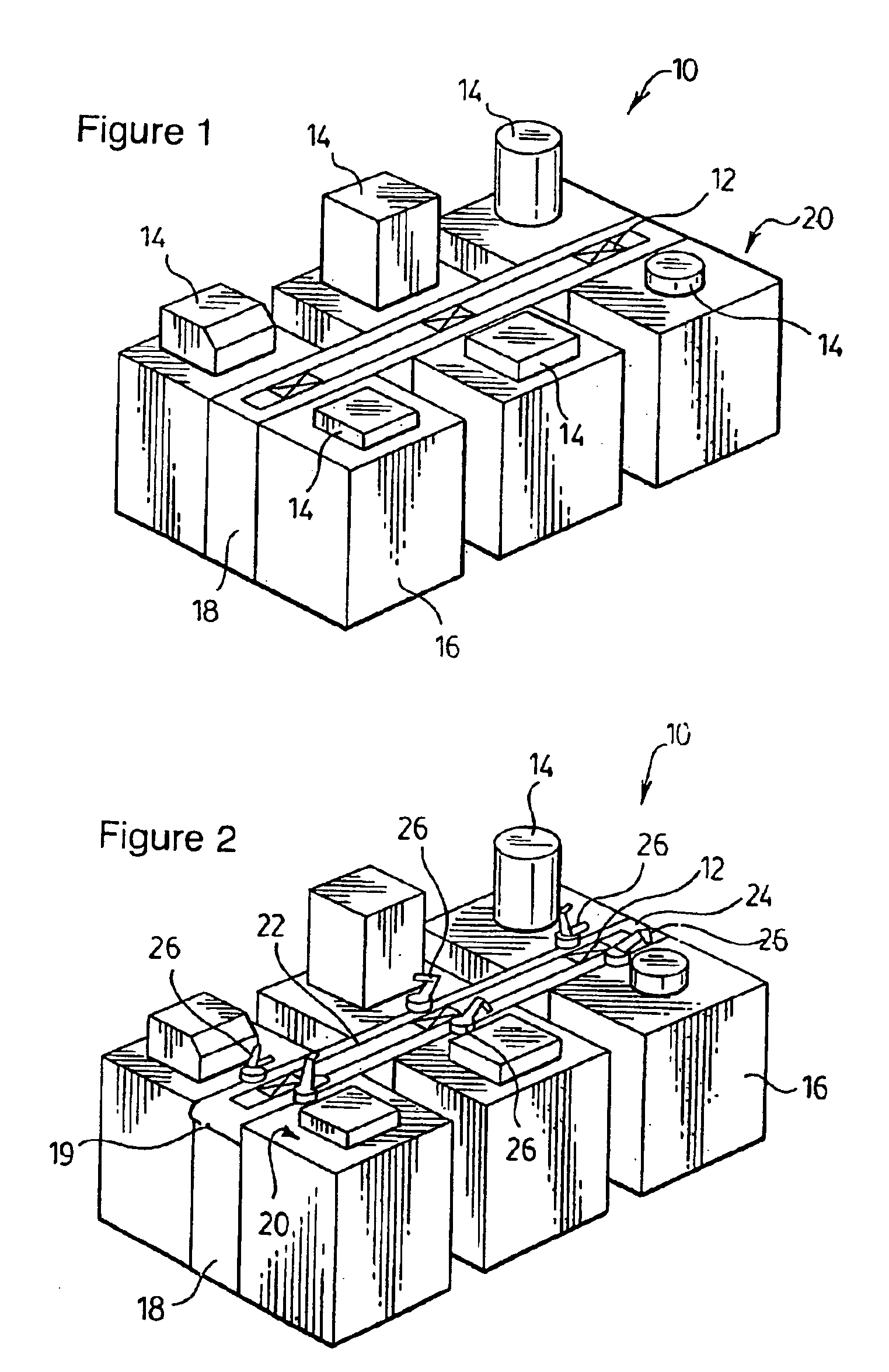
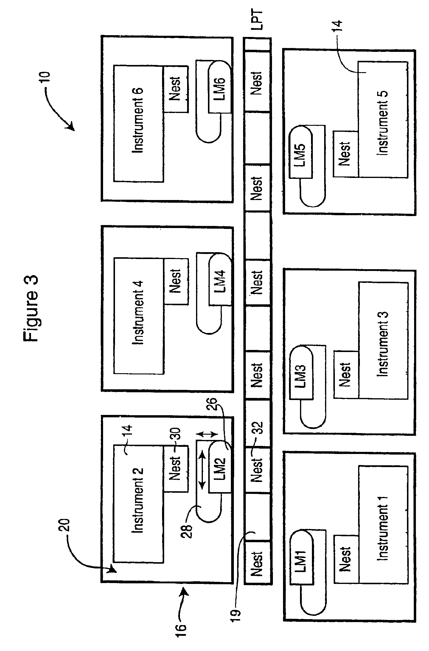
[0034]Referring to FIG. 1, a robotic system 10 is shown for processing a variety of samples 12 in a random flow by different process instruments 14. The robotic system 10 encompasses a method for processing the samples 12 using labware such as microtiterplates, filterplates, pipette-tip boxes and the like (not shown). The robotic system 10 has a modular architecture, consisting of a central backbone 18 and an arrangement of detachable modules 16 coupled to the backbone 18. The modules 16 carry the process instruments 14 for effecting a specific operation on the samples 12, preferably in sequence. The process instruments 14 can be mounted on a tabletop 20 of the modules 16, underneath the table 20, or on levels above the tabletop 20 as further described below. The structure of the robotic system 10 facilitates the attachment of the modules 16 on both sides of the backbone 18, meaning that one-sided or double-sided robotic systems 10 can be built. Preferably, the modules 16 represent ...


PUM

PropertyMeasurementUnit
lengthaaaaaaaaaa
support structureaaaaaaaaaa
heightsaaaaaaaaaa

Abstract

A method of processing objects using a bilateral architecture. The method comprises the steps of: arranging a plurality of instruments around a bi-directional conveyance device, the instruments spaced at fixed pitch intervals along the conveyor device; assigning dedicated movers to each of the instruments, the dedicated movers for loading and unloading of the objects to and from the instruments and the conveyance device; and controlling the operation of the conveyance device to have an interrupted motion, the interrupted motion for co-ordinating the loading and unloading of the objects; wherein the dedicated movers are positioned such that adjacent movers operate independently of one another. The method can be operated on an automated robotic system having a modular architecture. The system comprises; a backbone having a plurality of backbone connectors; a module having a module connector for releasably coupling with a respective one of the backbone connectors; a bi-directional motion device connected to the backbone, the motion device for presenting an object adjacent to the module when the module is coupled to the backbone; a connection interface formable by coupling the backbone and module connectors, the connection interface for providing an operation coupling between the backbone and the module when adjacent thereto; wherein the connection interface provides a repeatable connection and disconnection capability between the backbone and the module for ready reconfiguration of the modular architecture.

Description

[0001]This application claims priority from U.S. provisional application No. 60 / 350,943 filed on Jan. 25, 2002 and is a continuation of international application PCT / CA03 / 00106 filed on Jan. 27, 2003.BACKGROUND OF THE INVENTION[0002]1. Field of Invention[0003]The present invention relates to automated robotic systems, and in particular to adaptable processing of samples.[0004]2. Description of the Prior Art[0005]In recent years, researchers are beginning to use robotics and automation more frequently to address issues such as sample processing, throughput, and reliability of results. Automated sample handling is quickly becoming a necessity due to sterility requirements and desired cost reductions. Further motivation for automated handling is the introduction of new technologies, such as miniaturization, higher sample density storage, smaller sample volumes, and increased precision to name a few. It is common in industry to use robotic systems with a single robotic device to feed mu...

Claims


Application Information

Patent Timeline
Patent Type & Authority Patents(United States)
IPC IPC(8): G06F19/00B01L99/00G01N35/00G01N35/02G01N35/04
CPCG01N35/0092G01N35/0099G01N35/028G01N2035/0465G01N2035/00881G01N2035/0425G01N2035/00326
Inventor HAAS, HANSJOERG WERNERJONES, TREVOR GORDONHERTZ, ROGER BARRYMCCRACKIN, DANIEL CURTISOUTHOUSE, EDGAR ALLLISONHATHERLEY, THOMAS IANRIFF, MICHAEL PAULLOWE, GREGORY EARLHUBER, RICHARD ALEXANDERWITTCHEN, JONATHAN DAVIDKLINK, BRADLEY KENNETH
Owner THERMO CRS LTD
Learn More