Thermal breaking system for construction materials and the like

Active Publication Date: 2006-08-29
TRACO +1
23 Cites 26 Cited by

AI-Extracted Technical Summary

Problems solved by technology

A thermal break breaks the continuity of the framing system with the inclusion of a low conductance material thereby reducing conductivity of thermal energy.
Various problems exist that are associated with the poured and debridged process.
Further, the debridging of one piece extrusion generates a great deal of waste.
In the case of aluminum systems, high amounts of metal shavings must be discarded.
There is also a cost associated with the labor needed to perform the debridging process.
Further, the width of the thermal break is limited to the width of saw blades able to debridge one piece extrusions.
Thus, limitations...

Method used

[0021]Interposed between said first and second portions is a thermal insert (3A, B, C). The thermal insert is preferably made of a PVC, but can be made of nylon, polyamide, or fiberglass. The thermal insert is interposed between the first and second portions to define a longitudinal channel (6) having an opening. Preferably, said insert is frictionally connected to said portions by way of a tongue and groove configuration (7). However, it will be appreciated that the thermal insert may be connected to said portions by means of an adhesive, by the inserts having notches or nodes corresponding to depressions in each of said portions whereby the thermal section placed between said portions and said portions are knurled. In a preferred embodiment, the thermal insert has a longitudinal flange (5A, B, C) protruding the direction of the opening of the longitudinal channel. The flange increases the surface area of the thermal insert to which the thermal barrier (4) adheres, thereby increasing the adhesion strength of the thermal barrier to the thermal insert. The thermal barrier is to be integrally formed within the channel. More preferably, the thermal insert further comprises four side walls defining a hollow center, the hollow center space running the length of the insert. This embodiment of the thermal insert is shown at (3B) in FIG. 4. The hollow center space reduces thermal conductance further and further increases the acoustical properties of the system. In the embodiment, wherein the thermal insert is comprised of four side walls defining a hollow center space, it is preferable to provide the longitudinal flange, as depicted by (5B) in FIG. 4, on the side wall facing the opening in the longitudinal channel such that the flange protrudes in the direction of the opening that remains in the longitudinal channel. FIG. 5 shows another embodiment wherein a thermal insert (3C) further comprises a reinforcing member formed integra...

Benefits of technology

[0011]It is still yet an another object of the invention to reduce the number of dies necessary for extruded building components by providing for interchangeable extruded portions rather than one piece extrusions.
[0012]It is another object of the invention to allow for thermally broken building components to have portions of different color or texture without first painting the whole and then masking, and then separately painting the portion for which different texture is desired.
[0013]It is yet another object of the invention to eliminate waste caused by the “poured and debridging” process.
[...

Abstract

The invention comprises a thermal breaking system that can be used in the manufacture of windows, doors, and other building components. The thermal break system comprises first and second portions. Interposed between said portions is a thermal break. The thermal break and the portions define a longitudinal channel in which a thermal barrier is integrally formed. The thermal break can comprise a longitudinal flange to increase its adhesion to the thermal barrier. Further the thermal break can comprise four side walls that define a hollow center or void.

Application Domain

StrutsSpecial door/window arrangements +2

Technology Topic

Building materialEngineering +3

Image

  • Thermal breaking system for construction materials and the like
  • Thermal breaking system for construction materials and the like
  • Thermal breaking system for construction materials and the like

Examples

  • Experimental program(1)

Example

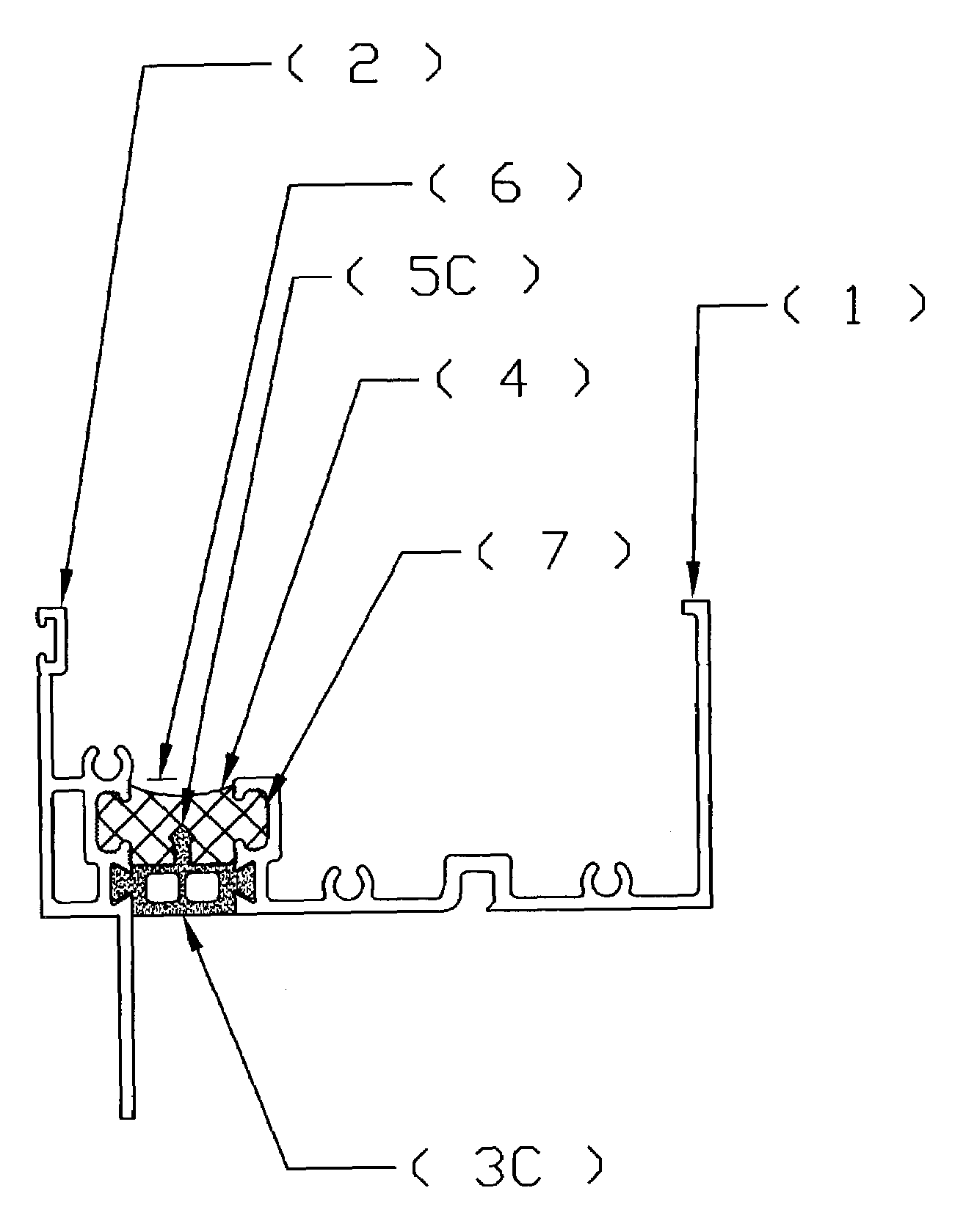
[0019]FIGS. 3, 4 and 5 show cross sections of a composite section that can be used in the manufacture of windows, door, and other construction and building components.
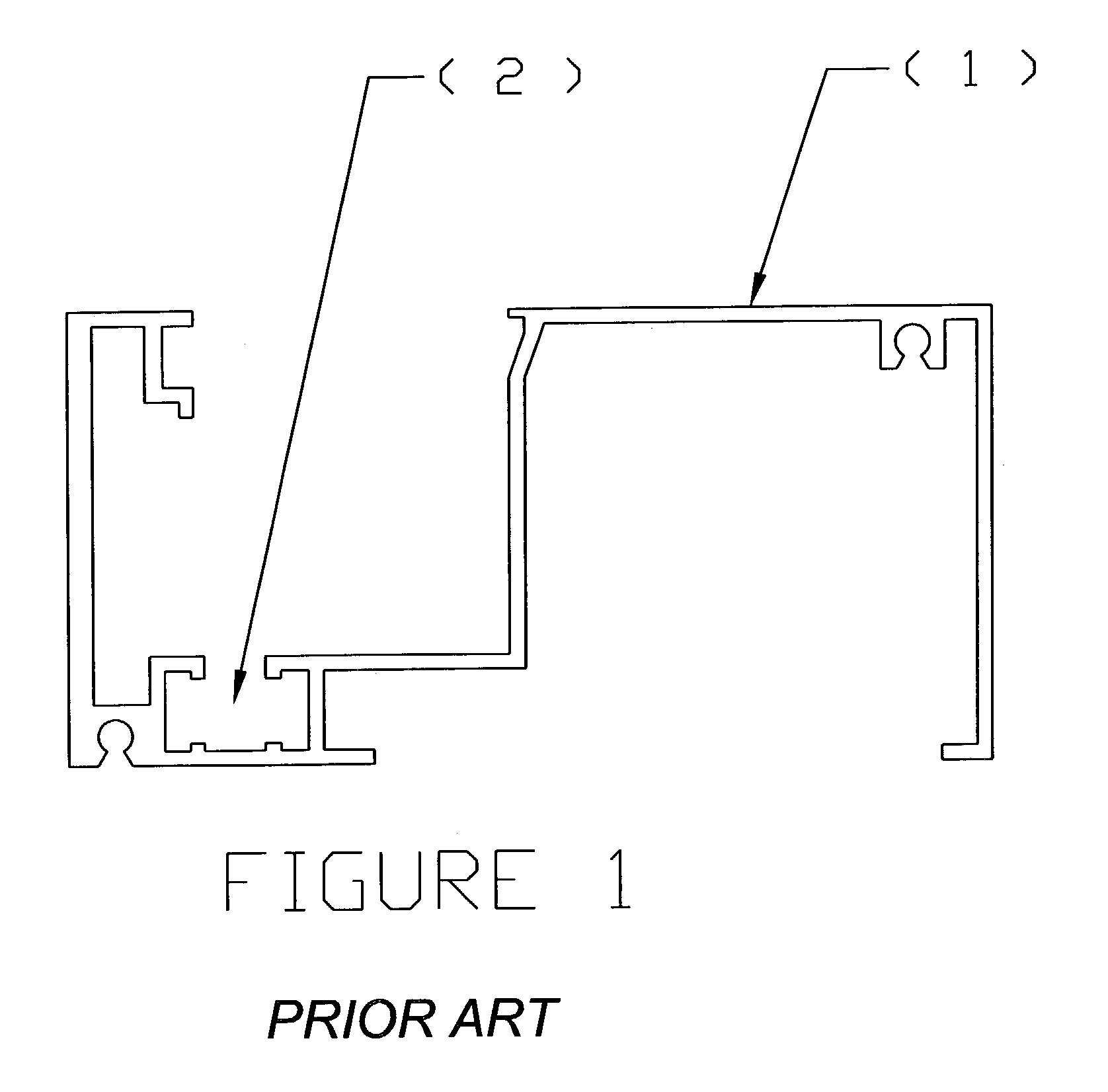
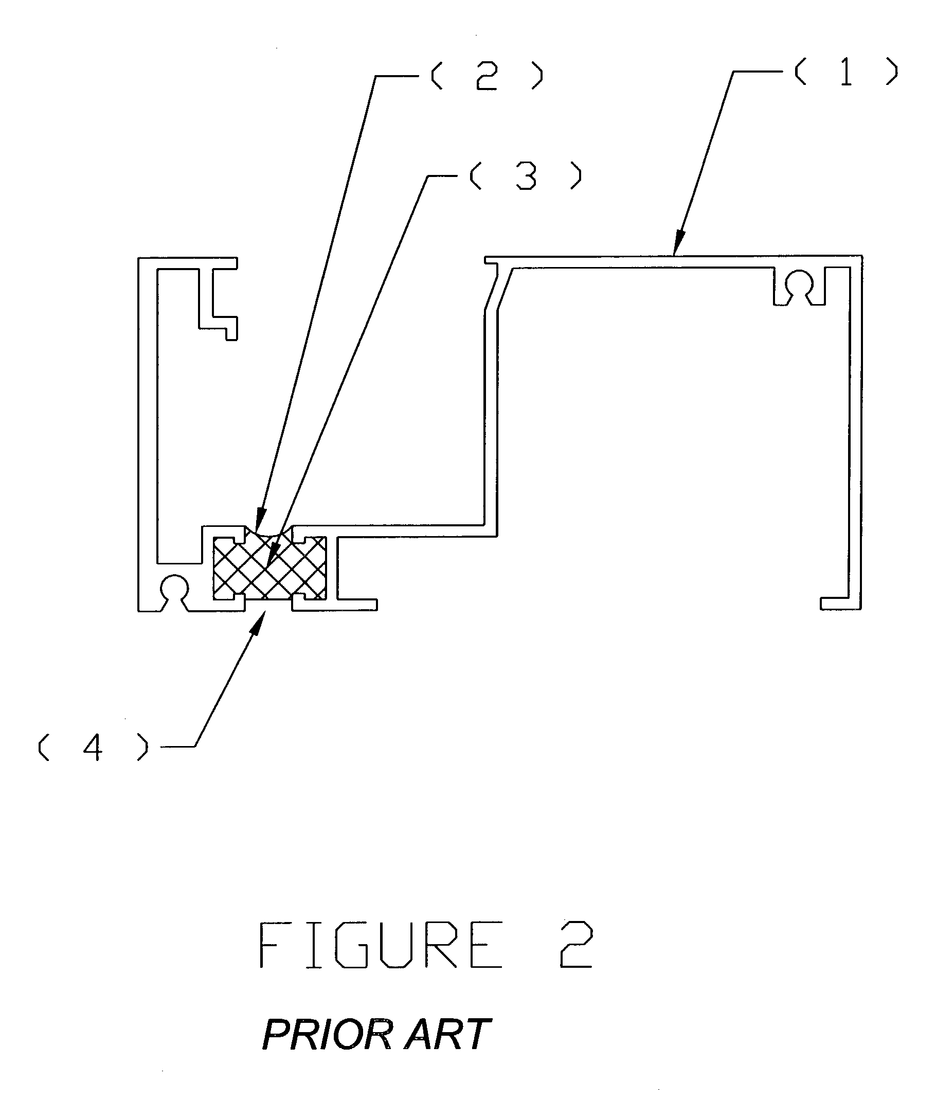
[0020]In the preferred embodiment, the thermal break system is made of a first (1) and a second (2) portion. Said portions can be made of, for example, aluminum or an aluminum alloy. Said portions correspond to the selections of the building component, i.e., windows, doors, etc., for which an interruption in the continuity of the building component is desired. Said interruption, of course, confers the benefit of lowering thermal conduction and enhancing the acoustical properties of the building components.
[0021]Interposed between said first and second portions is a thermal insert (3A, B, C). The thermal insert is preferably made of a PVC, but can be made of nylon, polyamide, or fiberglass. The thermal insert is interposed between the first and second portions to define a longitudinal channel (6) having an opening. Preferably, said insert is frictionally connected to said portions by way of a tongue and groove configuration (7). However, it will be appreciated that the thermal insert may be connected to said portions by means of an adhesive, by the inserts having notches or nodes corresponding to depressions in each of said portions whereby the thermal section placed between said portions and said portions are knurled. In a preferred embodiment, the thermal insert has a longitudinal flange (5A, B, C) protruding the direction of the opening of the longitudinal channel. The flange increases the surface area of the thermal insert to which the thermal barrier (4) adheres, thereby increasing the adhesion strength of the thermal barrier to the thermal insert. The thermal barrier is to be integrally formed within the channel. More preferably, the thermal insert further comprises four side walls defining a hollow center, the hollow center space running the length of the insert. This embodiment of the thermal insert is shown at (3B) in FIG. 4. The hollow center space reduces thermal conductance further and further increases the acoustical properties of the system. In the embodiment, wherein the thermal insert is comprised of four side walls defining a hollow center space, it is preferable to provide the longitudinal flange, as depicted by (5B) in FIG. 4, on the side wall facing the opening in the longitudinal channel such that the flange protrudes in the direction of the opening that remains in the longitudinal channel. FIG. 5 shows another embodiment wherein a thermal insert (3C) further comprises a reinforcing member formed integrally within said hollow space.
[0022]Formed integrally in the longitudinal channel is the thermal barrier (4). The thermal barrier, in a preferred embodiment, is made of polyurethane and occupies the space of the channel such that it comes in contact with and is integral with the first (1) and second (2) portion and the wall of the thermal insert that faces the channel (6) opening. In a preferred embodiment, the thermal barrier is formed integrally by pouring elastomeric material, more preferably polyurethane, in said channel in an amount to fill the channel. Once hardened, the elastomeric material or polyurethane acts as a thermal barrier to reduce thermal conductance between said portions and to increase the acoustic properties. The width and volume of the thermal barrier can be varied by altering the distance between the first and second portions or the depth of the longitudinal channel. In this way, the invention possesses the desirable characteristics of being able to be widened at-will, and in a way that is not dependent on the width of the debridging saw blade, as is the case in poured and debridged systems. The distance of the thermal break (which is the distance between the points where the first and second portions contact the thermal insert, or in other words, the width of the thermal insert) can be from ⅛ to 1 inch and is preferably ½ inch. In an embodiment using polyurethane, the polyurethane strongly adheres to the thermal insert and the first and second portions to the point of becoming integral or substantially integral therewith. By substantially integral it is meant the thermal barrier adheres very strongly with the thermal insert and the first and second portions and is formed into, and occupies, the space of the longitudinal channel. However, the skilled artisan will of course appreciate that in some cases, with sufficient labor, the barrier could be removed or separated from the first and second portions.
[0023]While presently preferred embodiments have been described and shown, the invention may be otherwise embodied within the scope of the appended claims.

PUM

no PUM

Description & Claims & Application Information

We can also present the details of the Description, Claims and Application information to help users get a comprehensive understanding of the technical details of the patent, such as background art, summary of invention, brief description of drawings, description of embodiments, and other original content. On the other hand, users can also determine the specific scope of protection of the technology through the list of claims; as well as understand the changes in the life cycle of the technology with the presentation of the patent timeline. Login to view more.

Similar technology patents

Forensic system, forensic method, and forensic program

InactiveUS20160110826A1reduce numberreduce user burden
Owner:FRONTEO INC

Methods and interferon deficient substrates for the propagation of viruses

InactiveUS6573079B1reduce viral titerreduce number
Owner:MT SINAI SCHOOL OF MEDICINE

Classification and recommendation of technical efficacy words

  • reduce number
  • eliminate waste

Programming non-volatile memory

ActiveUS6888758B1short program timereduce number
Owner:SANDISK TECH LLC

Personalized display of health information

InactiveUS20050027562A1reduce number
Owner:HEALTH HERO NETWORK

Display device

Owner:SEMICON ENERGY LAB CO LTD

System and method for automating generation of an automated sensor network

ActiveUS20080059947A1eliminate waste
Owner:EATON INTELLIGENT POWER LIMITED

Method and equipment for cultivating anaerobic ammonium-oxidizing bacteria

ActiveUS20060205055A1eliminate wasteefficient cultivation
Owner:HITACHI LTD

Circular or annular coating film forming method

InactiveCN1365302Aeliminate waste
Owner:CHUGAI RO CO LTD

Apparatus and/or kit related to smartphone cases

InactiveUS20150018056A1eliminate waste
Owner:TANUKI ENTERTAINMENT

Method for reconditioning barrels

InactiveUS20110203093A1eliminate wasteeliminate possibility
Owner:RE WINE BARRELS
Why Eureka
Try Eureka