Rotating blast liner

a technology of rotating blast liner and rotating shaft, which is applied in the direction of drilling pipe, drilling casing, and accessories of wellbore/well, etc., can solve the problems of axial movement of blast liner, further increase of impingement or wear area of blast liner, etc., to increase the impingement or wear area, prolong the life of blast liner, and increase the impingement area. effect of area

Inactive Publication Date: 2006-08-29
BAKER HUGHES INC
View PDF18 Cites 78 Cited by
  • Summary
  • Abstract
  • Description
  • Claims
  • Application Information

AI Technical Summary

Benefits of technology

[0008]The blast liner is a cylindrical member that provides a protective shield to the interior retaining section. It is typically fashioned from a hardened, resilient material, such as 4140 steel. The blast liner includes an impingement area that may be coated with a protective coating, such as a ceramic or tungsten coating. Additionally, an angular flow diverter is provided within the blast liner, preferably proximate the lower end. In preferred embodiments, the flow diverter is a plurality of angled flow diversion channels formed into the inner surface of the lower end of the blast liner body. The flow diversion channels may be provided by several radially inwardly-projecting vanes or, in the alternative, grooves that are milled into the interior surface of the lower end. Flow of slurry through the blast liner will cause the blast liner to rotate within the retaining section due to the reaction forces imparted to the blast liner from diverting the slurry flow. In this manner, the impingement area presented by the blast liner is increased, and the life of the blast liner extended.
[0009]Several exemplary constructions for a rotatable blast liner assembly are described herein. In one embodiment, the liner is rotatable within a fixed axial space in the retaining section. Bearing members are disposed between the blast liner and the retaining section to assist rotation. In a second described embodiment, the blast liner assembly includes a wearable, or erodable, bushing that is disposed below the blast liner in the liner retaining section. As the liner rotates within the liner retaining section, the bushing wears away, resulting in axial movement of the blast liner within the liner retaining section. This axial movement further increases the impingement or wear area provided by the blast liner. In a further described embodiment, the liner retaining section is provided with a circuitous lug track and the blast liner is provided with an outwardly projecting lug that resides within the lug track. Rotation of the blast liner within the liner retaining section thereby results in controlled axial movement of the blast liner within the liner retaining section. Again, the axial movement of the blast liner acts to increase the impingement or wear area provided by the blast liner.

Problems solved by technology

As the liner rotates within the liner retaining section, the bushing wears away, resulting in axial movement of the blast liner within the liner retaining section.
This axial movement further increases the impingement or wear area provided by the blast liner.

Method used


Image

  • Rotating blast liner
  • Rotating blast liner
  • Rotating blast liner

Examples


Embodiment Construction

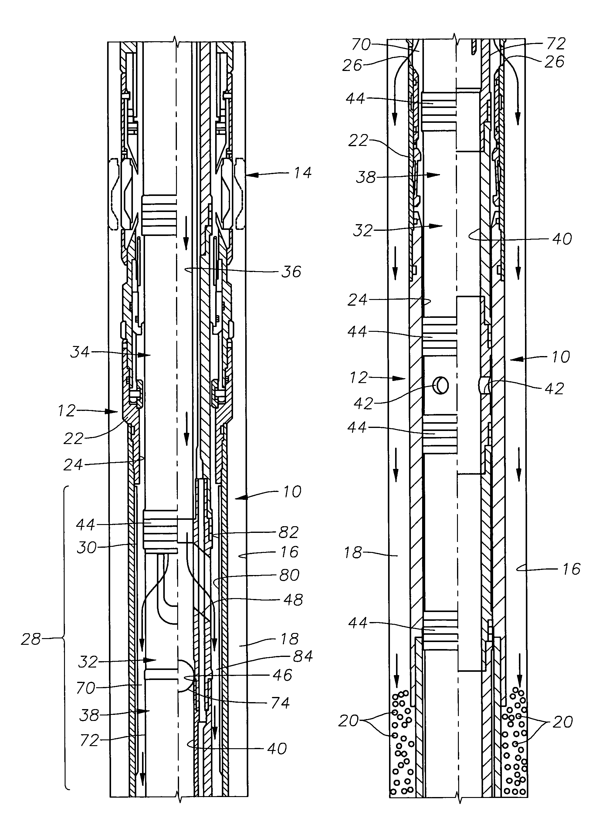
[0018]FIGS. 1a and 1b depict an exemplary solids placement system 10, which includes an extension sleeve assembly 12 that is secured to the lower end of a packer assembly 14. The exemplary solids placement system 10 is a system for the placement of gravel within a wellbore 16 during gravel packing. However, those of skill in the art will appreciate that a similar arrangement may be used for disposal of proppants and other solids within a wellbore. It is noted that the details of gravel packing and proppant placement operations generally are well known to those of skill in the art and, therefore, will not be described in detail herein. However, the general outline of an exemplary gravel packing tool and system 10 is described in order to illustrate one use of the blast liner assembly of the present invention.

[0019]The packer assembly 14 is a through-tubing packer assembly in that, once set, it can permit a service tool to be passed through its axial center. At the beginning of a grav...


PUM


Abstract

An improved blast liner assembly for use in gravel packing or fracturing operations wherein solid materials, in slurry form, are flowed out of the flowbore of a working tool and into the annulus of a wellbore. The blast liner is a cylindrical member that provides a protective shield to the interior retaining section. An angular flow diverter is provided within the blast liner and has a plurality of angled flow diversion channels formed into the inner surface of the blast liner body. Flow of slurry through the blast liner will cause the blast liner to rotate within the retaining section due to the reaction forces imparted to the blast liner from diverting the slurry flow. In this manner, the impingement area presented by the blast liner is increased, and the life of the blast liner extended. The blast liner may also be caused to move axially within the retaining section to further increase the impingement area.

Description

BACKGROUND OF THE INVENTION[0001]1. Field of the Invention[0002]The invention relates generally to devices and methods for improved fracturing and / or gravel packing operations within a wellbore. In more particular aspects, the invention relates to the protection of devices that are used to place gravel or proppants in such operations.[0003]2. Description of the Related Art[0004]There are times during the life of a well that it is necessary to flow granular or pelletized solid materials, in a slurry, into a wellbore in order to improve wellbore operation or to extend the life of the well. Two of the more common techniques are gravel packing and fracturing of a formation using a fracturing fluid having proppant therein. During gravel packing, gravel is pumped down a tubing string into a wellbore and placed, where desired, using a cross-over tool with suitable exit ports for placement of the gravel in desired locations within the wellbore. In fracturing operations, a fracturing agent i...

Claims


Application Information

Patent Timeline
Patent Type & Authority Patents(United States)
IPC IPC(8): E21B43/04E21B17/10E21B43/267
CPCE21B17/1007E21B43/267E21B43/045E21B17/1085E21B17/10E21B43/04
Inventor JASSER, RAMI J.CORONADO, MARTIN P.SALERNI, JOHN V.NELSON, JOHN A.
Owner BAKER HUGHES INC
Why Eureka
Try Eureka