Light source unit for vehicular lamp

a technology for vehicular lamps and light sources, which is applied in the direction of lighting support devices, lighting and heating apparatus, instruments, etc., can solve the problems of not teaching a light source suitable for use in a vehicular headlamp, and the reduction of the size of the lighting unit cannot be achieved with the conventional projection-type vehicular lamps, so as to achieve the effect of significantly reducing the size of the vehicular lamps

Inactive Publication Date: 2006-08-29
KOITO MFG CO LTD
View PDF23 Cites 68 Cited by
  • Summary
  • Abstract
  • Description
  • Claims
  • Application Information

AI Technical Summary

Benefits of technology

[0012]In consideration of the problems mentioned above, it is an object of the invention to ...

Problems solved by technology

However, in the conventional projection-type vehicular lamp where a discharge light-emitting section of a discharge bulb or a filament of a halogen bulb is used for a light source thereof, the following problem occurs.
From the foregoing, there is...

Method used


Image

  • Light source unit for vehicular lamp
  • Light source unit for vehicular lamp
  • Light source unit for vehicular lamp

Examples


first embodiment

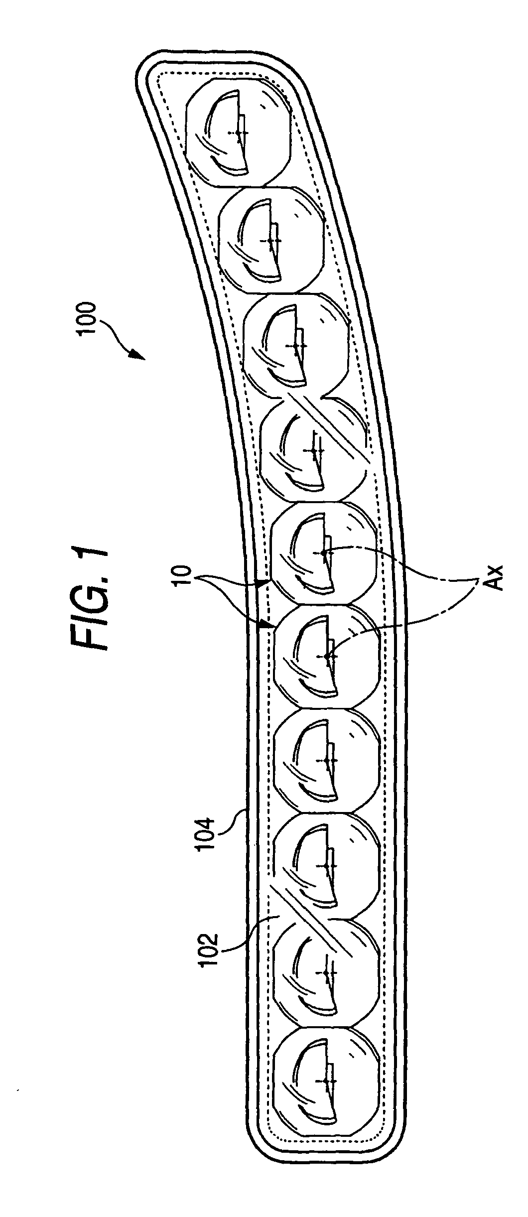
[0048]FIG. 1 is a front view showing a vehicular lamp 100 which incorporates a light source unit 10 constructed according to the invention.

[0049]The lighting unit 100 is a low-beam headlamp incorporating ten light source units 10 arranged in a substantially horizontal line in a lamp housing formed by a transparent cover 102 and a lamp body 104.

[0050]The light source units 10, which all have the same structure, are accommodated in the lamp housing with their optical axes Ax extending generally in the longitudinal direction of the vehicle, more specifically, in a downward direction by approximately 0.5 to 0.6 degree with respect to the longitudinal direction of the vehicle.

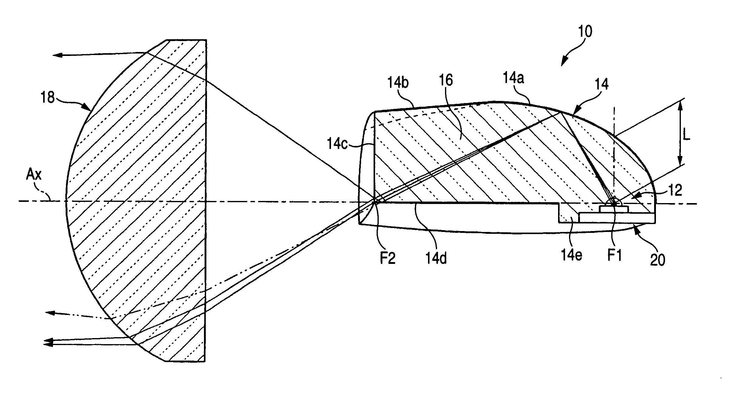
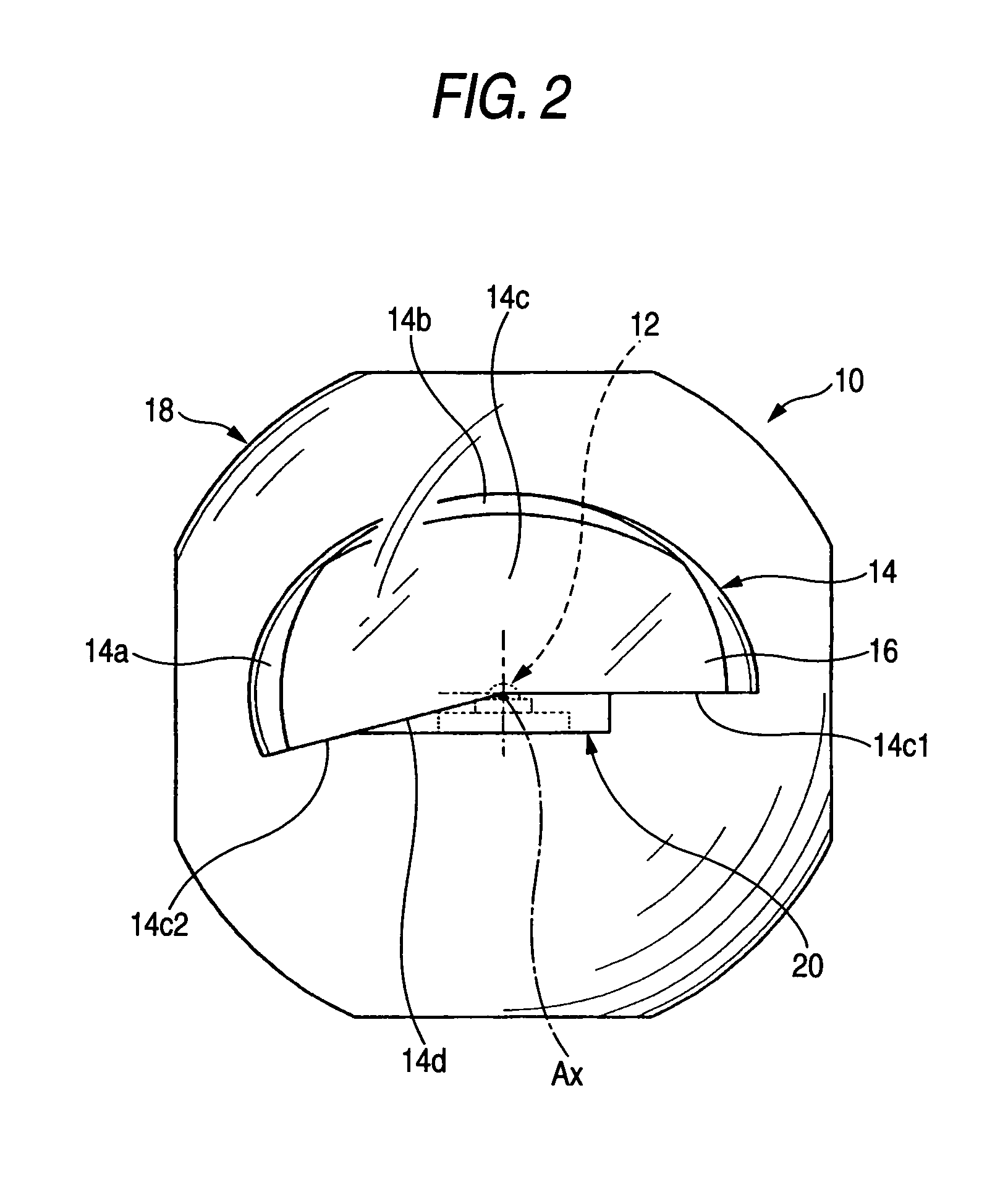
[0051]FIG. 2 is a front view showing a single light source unit 10, and FIGS. 3 and 4 are sectional side and plan views, respectively, of the light source unit 10.

[0052]As shown in these drawings, the light source unit 10 includes an LED 12 (a semiconductor light-emitting element) as a light source, a reflector 14, ...

second embodiment

[0086]Next, the embodiment will be described.

[0087]FIG. 8 is a sectional side view showing a light source unit 10A according to the second embodiment.

[0088]As shown in FIG. 8, the light source unit 10A employs different structures for the translucent block 16A and projection lens 18A than those of the translucent block 16 and the projection lens 18 according to the first embodiment, while other structures are the same as those in the first embodiment.

[0089]In the translucent block 16A, the shape of an emitting end face 14c is the same as that of the translucent block 16 (shown by a two-dot chain line in the drawing) according to the first embodiment, but a third reflecting surface 14Ad is inclined slightly upward and rearward from the emitting end face 14c. The angle of inclination a may be approximately 1 to 10 degrees, for example.

[0090]With the third reflecting surface 14Ad formed as described above, the angle at which light is reflected upward by the third reflecting surface 14A...

third embodiment

[0113]Next, a light source unit of the invention will be described.

[0114]FIG. 13 is a sectional side view showing a light source unit 30 according to the third embodiment.

[0115]The light source unit 30 is designed for providing a high-beam light distribution pattern.

[0116]More specifically, as in the previously disclosed embodiments, the light source unit 30 according to the third embodiment has a reflector 34 constituted by a reflective coating formed over the surface of a translucent block 36 which covers an LED 12. In the third embodiment, however, the emitting end face 34c of the translucent block 36 is not fan-shaped as in the previously described embodiments, and the lower edge of the emitting end face 34c is at a significantly lower position than the lower edge of the emitting end face 14c according to the first two embodiments.

[0117]Moreover, a fourth reflecting surface 34d inclined forward and downward is formed on the lower end of the translucent block 36 in place of the t...


PUM


Abstract

A light source unit capable of considerably reducing the size of a vehicular lamp. An LED is mounted on an optical axis extending in the longitudinal direction of the vehicle with its light output directed upward, and a reflector is provided above the LED having a first reflecting surface for collecting the light emitted by the LED and reflecting the light generally in the direction of the optical axis Ax. The reflector is formed by a reflective coating formed on the surface of a translucent block covering the LED. Consequently, the size of the reflector can be considerably reduced as compared with reflectors employed in conventional vehicular lamps. Moreover, since the LED used as a light source emits little heat, the reflector can be designed without having to take into account the influence of heat generated by the light source. Furthermore, the LED can be treated substantially as a point light source so that proper reflection control can be carried out even if the size of the reflector is reduced. By mounting the LED so that its light output is directed substantially orthogonal to the optical axis Ax, moreover, it is possible to effectively utilize most of the light emitted by the LED and reflected by the first reflecting surface.

Description

CROSS-REFERENCE TO RELATED APPLICATIONS[0001]Not applicableSTATEMENT REGARDING FEDERALLY SPONSORED RESEARCH OR DEVELOPMENT[0002]Not applicableREFERENCE TO SEQUENCE LISTING, A TABLE, OR A COMPUTER PROGRAM LISTING COMPACT DISK APPENDIX[0003]Not applicableBACKGROUND OF THE INVENTION[0004]The present invention relates to a light source unit for use in a vehicular lamp.[0005]Conventionally, a so-called projection-type vehicular lamp implemented as a headlamp has been known.[0006]In a projection-type vehicular lamp, light emitted by a light source disposed on the optical axis of the lamp is collected and reflected forward in the direction of the optical axis by a reflector, and the reflected light is radiated in the forward direction of the lighting unit through a projection lens mounted in front of the reflector.[0007]By employing such a projection-type vehicular lamp it is possible to reduce the overall size of the lighting unit compared with a so-called parabolic-type vehicular lamp.[0...

Claims


Application Information

Patent Timeline
IPC IPC(8): F21V7/04F21S8/10F21S8/12F21V5/00F21V7/00F21V8/00F21V13/00F21W101/10F21Y101/02
CPCF21S48/1159F21S48/1163F21S48/1329F21S48/1241F21V2200/00F21Y2101/02F21S48/125F21Y2115/10F21S41/155F21S41/24F21S41/25F21S41/322F21S41/16F21S41/151F21S41/148F21S41/33F21S41/141F21W2102/00F21Y2105/10
Inventor ISHIDA, HIROYUKITATSUKAWA, MASASHI
Owner KOITO MFG CO LTD
Why Eureka
Try Eureka