Cooling system for an airfoil vane

a cooling system and airfoil technology, applied in the field of hollow turbine vanes, to achieve the effect of reducing heat, reducing the likelihood of failure, and improving the overall cooling effect of the turbine van

Active Publication Date: 2006-08-29
SIEMENS ENERGY INC
View PDF27 Cites 57 Cited by
  • Summary
  • Abstract
  • Description
  • Claims
  • Application Information

AI Technical Summary

Benefits of technology

[0008]An advantage of this invention is that the vortex forming chambers reduce heat from the fillet region at the intersection of an airfoil and an endwall, thereby reducing the likelihood of failure at this locale.
[0009]Another advantage of this invention is that the cooling injection holes may be sized based upon supply and discharge pressures of the cooling system.
[0010]Yet another advantage of this invention is that the vortex forming chambers and other components of the cooling system result in a higher overall cooling effectiveness of a turbine vane as compared with conventional designs at least because the vortex chambers result in a higher heat transfer convection coefficient of the cooling fluids.
[0011]Still another advantage of this invention is that the film cooling holes may be placed in close proximity to the fillet, which enables the temperature of the fillet region to be reduced.

Problems solved by technology

In addition, turbine vanes often contain cooling systems for prolonging the life of the vanes and reducing the likelihood of failure as a result of excessive temperatures.

Method used


Image

  • Cooling system for an airfoil vane
  • Cooling system for an airfoil vane
  • Cooling system for an airfoil vane

Examples


Embodiment Construction

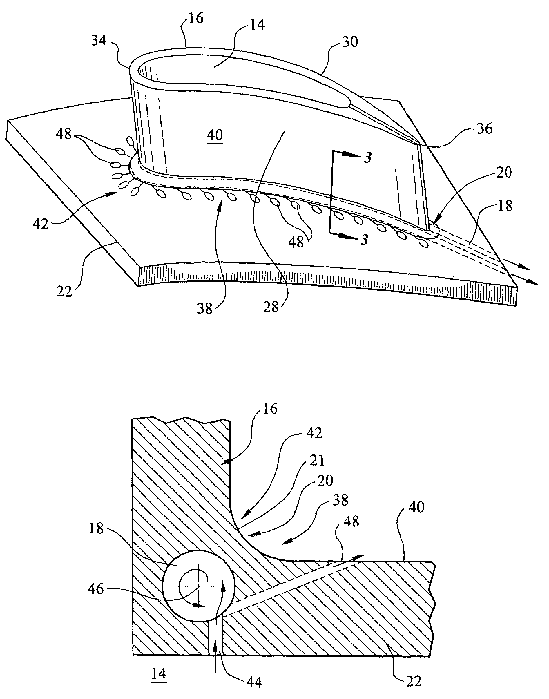
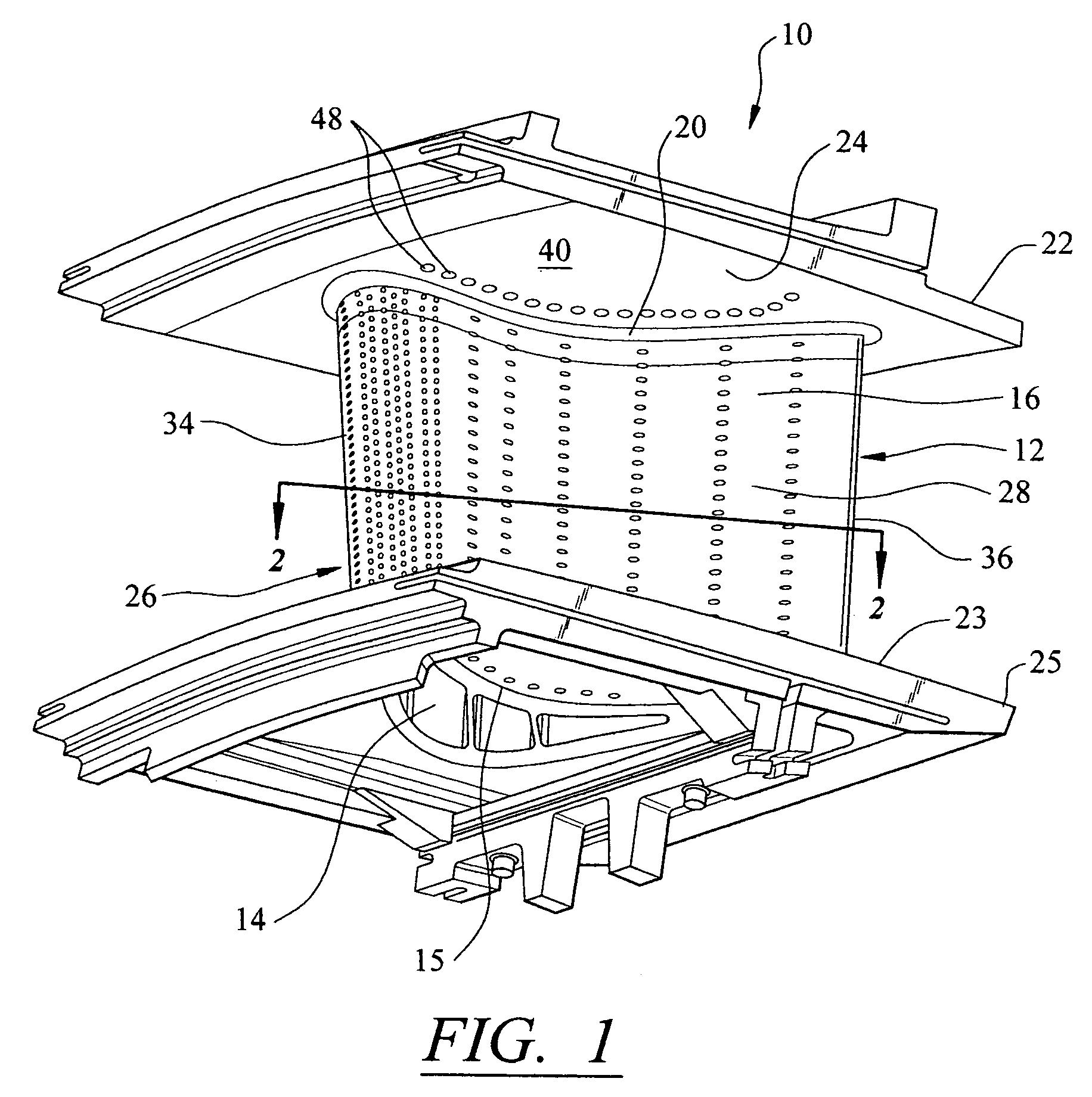
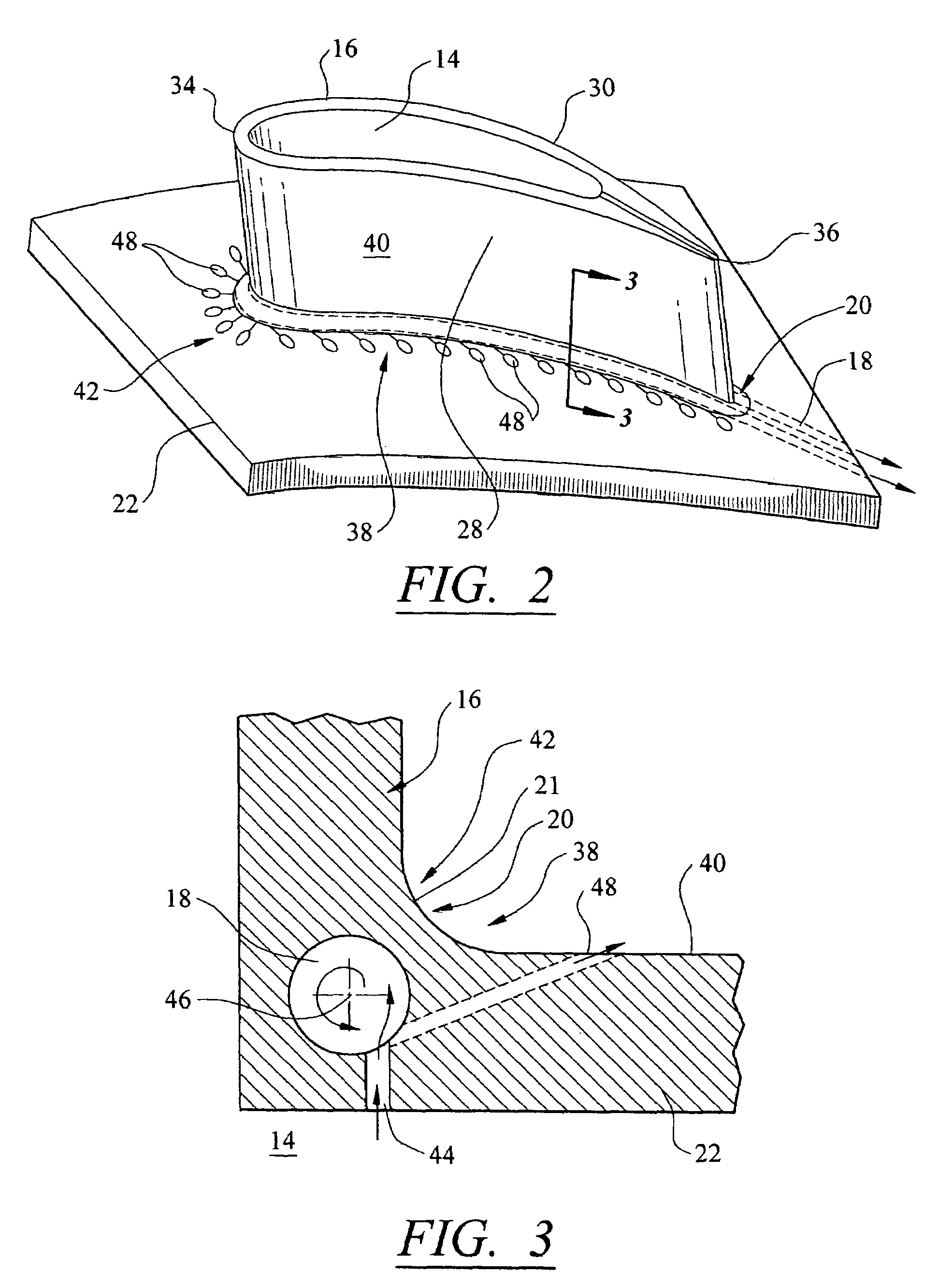
[0017]As shown in FIGS. 1–3, this invention is directed to a turbine vane cooling system 10 usable in internal cooling systems of turbine vanes 12 of turbine engines. In particular, turbine vane cooling system 10 is directed to a cooling system 10 formed at least from a cavity 14, as shown in FIG. 2, positioned between outer walls 16. The cooling system 10 may include one or more vortex forming chambers 18 for cooling aspects of the outer wall 16 at an intersection 20 between the outer wall 16 and an endwall 22. As shown in FIG. 1, the turbine vane 12 may be formed from a first endwall 22 at a first end 24 and a generally elongated airfoil 26 coupled to the first endwall 22 at the intersection 20 opposite a second endwall 23 at a second end 25. Intersection 20 may include a fillet 21 for providing a transition between the airfoil 26 and the first or second endwalls 22, 23. The fillet 21 may provide additional strength to the connection between the airfoil 26 and the first or second ...


PUM


Abstract

A turbine vane for a turbine engine having a cooling system in inner aspects of the turbine vane. The cooling system includes one or more vortex forming chambers proximate to the intersection of an airfoil forming a portion of the turbine vane and an endwall to which the airfoil is attached. The intersection of the airfoil and the endwall may include a fillet for additional strength at the connection. The vortex forming chambers receive cooling fluids from cooling injection holes that provide a cooling fluid supply pathway between the cooling air supply cavity and the vortex forming chambers. The cooling fluids may be exhausted through one or more film cooling holes. The film cooling holes may exhaust cooling fluids proximate to the fillet to reduce the temperature of the external surface of the fillet and surrounding region.

Description

FIELD OF THE INVENTION[0001]This invention is directed generally to airfoil vanes, and more particularly to hollow turbine vanes having internal cooling channels for passing gases, such as air, to cool the vanes.BACKGROUND[0002]Typically, gas turbine engines include a compressor for compressing air, a combustor for mixing the compressed air with fuel and igniting the mixture, and a turbine vane assembly for producing power. Combustors often operate at high temperatures that may exceed 2,500 degrees Fahrenheit. Typical turbine combustor configurations expose turbine vane assemblies to these high temperatures. As a result, turbine vanes must be made of materials capable of withstanding such high temperatures. In addition, turbine vanes often contain cooling systems for prolonging the life of the vanes and reducing the likelihood of failure as a result of excessive temperatures.[0003]Typically, turbine vanes are formed from an elongated portion forming a vane having one end configured ...

Claims


Application Information

Patent Timeline
Patent Type & Authority Patents(United States)
IPC IPC(8): F01D25/12F01D5/14
CPCF01D5/145F05B2240/801F05D2240/81
Inventor LIANG, GEORGE
Owner SIEMENS ENERGY INC
Why Eureka
Try Eureka