Cauterizing scalpel blades

a scalpel blade and scalpel technology, applied in the field of surgical cutting instruments, can solve the problems of limited cauterizing ability, undesired blood flow, and the cutting of tissue of patients' tissue accompanied by the cutting of tissu

Inactive Publication Date: 2006-08-29
UOP LLC
View PDF29 Cites 17 Cited by
  • Summary
  • Abstract
  • Description
  • Claims
  • Application Information

AI Technical Summary

Problems solved by technology

However, the cutting of a patient's tissue is also usually accompanied by an undesired flow of blood from small blood vessels within the tissue.
The vibration generates ultrasound waves for heating the tissue, however, there is only limited cauterizing ability.

Method used


Image

  • Cauterizing scalpel blades
  • Cauterizing scalpel blades
  • Cauterizing scalpel blades

Examples


first embodiment

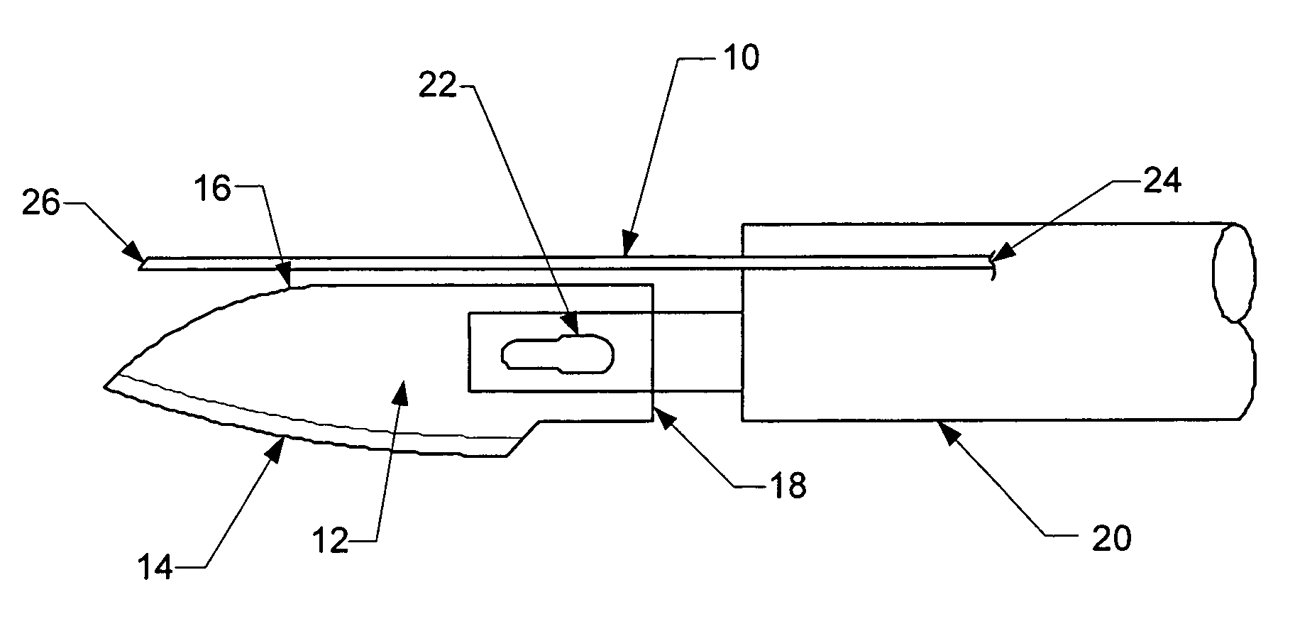
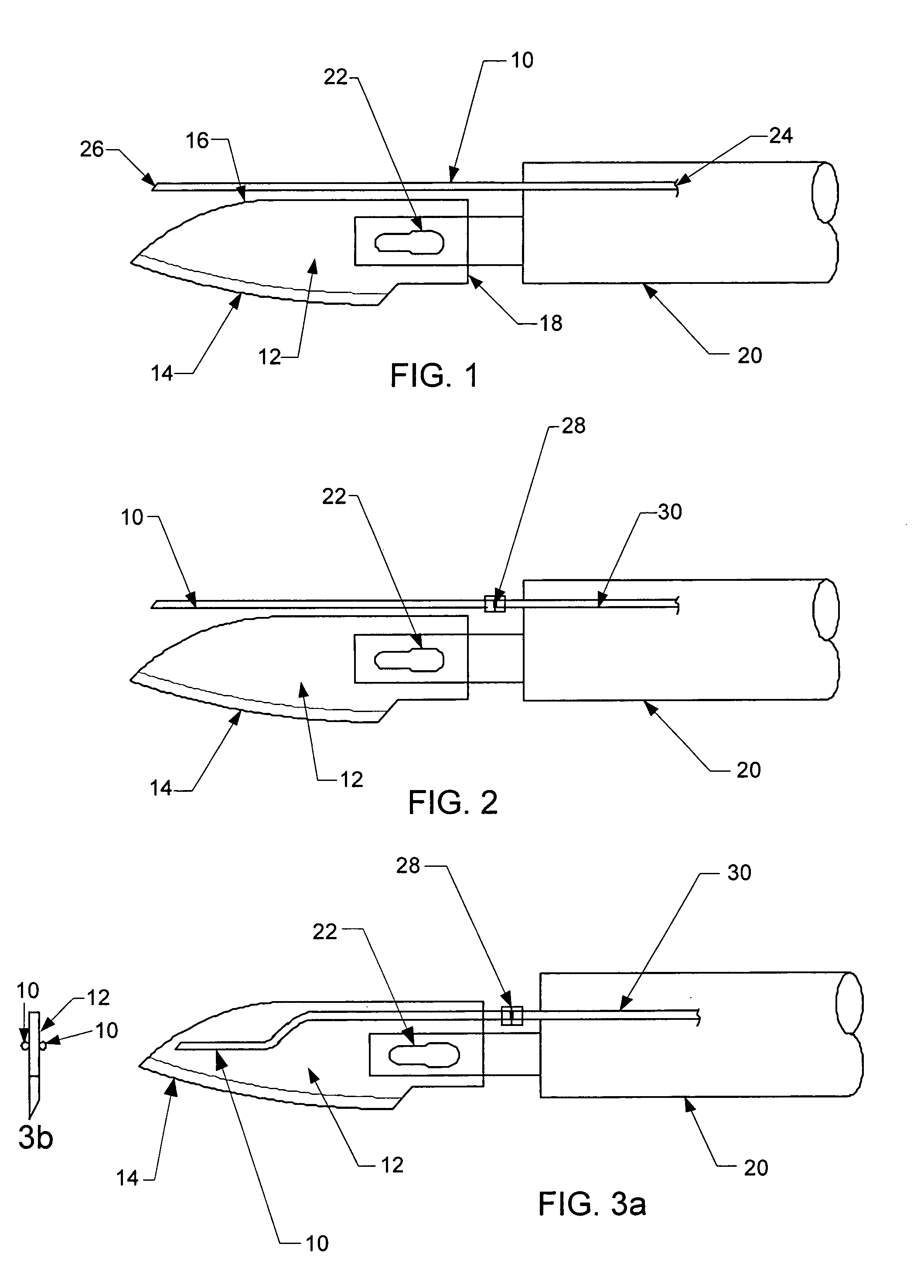
[0029]the present invention, as shown in FIG. 1, comprises a conduit in the form of a needle 10 in close proximity to a scalpel blade 12. The blade 12 has a cutting edge 14, a non-cutting edge 16, and an edge 18 distal to the cutting edge 14. The embodiment includes a handle 20 and a means 22 for releasably attaching the blade 12. The needle 10 has an inlet 24 and an outlet 26, and is affixed to the handle 20 in a manner such that the outlet 26 is in a predetermined position relative to the blade 12. The needle further includes a catalyst disposed near the needle outlet 26. This embodiment positions the source of heat near the non-cutting edge 16 of the scalpel blade 12. The needle 10 has an inner diameter of less than 400 micrometers with the inner diameter preferably about 200 micrometers. As used hereinafter, the term needle will mean a conduit of any form that meets the limitations on the inner diameter.

[0030]A gas mixture flows from a conduit inlet 24 through the conduit 10 and...

third embodiment

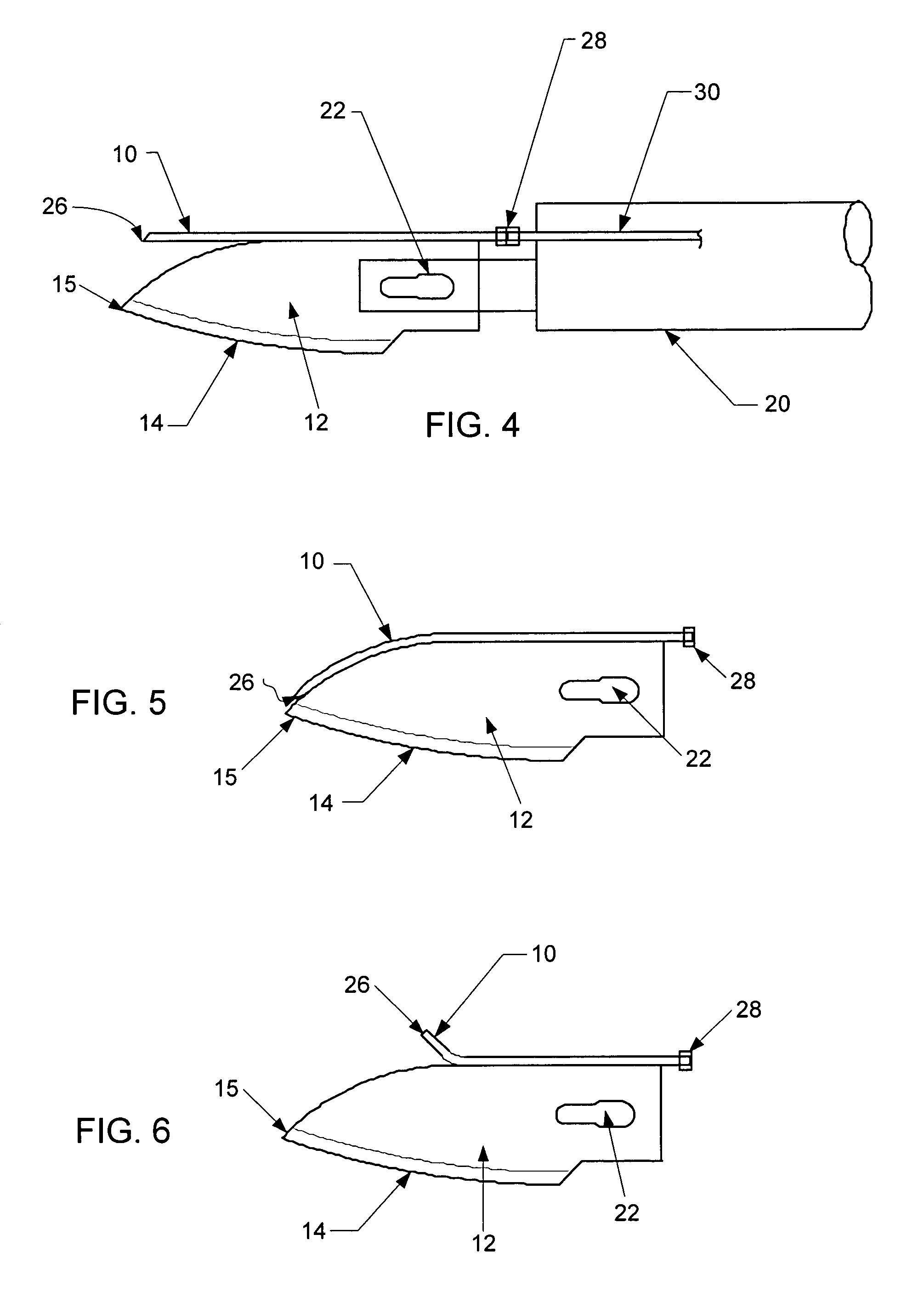
[0034]FIGS. 4, 5, and 6 show various configurations for the needle 10 relative to the blade 12. The needle 10 can be affixed to the blade 12 for further rigidity in holding the needle 10 in a fixed orientation relative to the blade 12, creating a needle-blade assembly. In this embodiment, a portion of the needle 10 is affixed along the non-cutting edge of the blade 12, allowing for the outlet 26 of the needle to be positioned either near the tip 15 of the blade as in FIG. 5, or away from the tip 15 as in FIG. 6. The needle-blade assembly is releasably attached to the handle 20 via two connections, a blade mount 22 and a needle fitting 28. The needle 10 can be affixed to the blade 12 by any suitable process, and includes welding, brazing, soldering, and adhesives. As shown in the FIGS. 4–6, the needle 10 is bent or straight to provide heat release at the tip 15 of the blade 12, or at some position removed from the cutting edge 14. The use of a needle 10 with the heat release at the b...


PUM


Abstract

An apparatus is disclosed for cutting and cauterizing of tissue. The apparatus comprises a cutting edge of a blade. The apparatus further comprises a conduit having a catalyst located near the conduit outlet, and the conduit is for delivering a combustible mixture of gases. The gases react in the presence of the catalyst and generate heat. The heat generated cauterizes blood vessels when applied to the cut tissue.

Description

CROSS-REFERENCE TO RELATED APPLICATIONS[0001]This application is a Continuation-In-Part of U.S. application Ser. No. 10 / 253,866, filed Sep. 24, 2002, now U.S. Pat. No. 6,832,995, which is a Continuation-In-Part of U.S. application Ser. No. 10 / 200,794, filed Jul. 22, 2002, now U.S. Pat. No. 6,824,555, all of which are incorporated by reference.FIELD OF THE INVENTION[0002]The present invention relates to surgical cutting instruments. In particular, this invention relates to scalpels that incorporate means for cauterizing blood vessels during usage of the scalpel.BACKGROUND OF THE INVENTION[0003]Surgical operations often involve the cutting of a patient's tissue. Usually, the tissue is cut with a scalpel, a sharp edged cutting instrument. However, the cutting of a patient's tissue is also usually accompanied by an undesired flow of blood from small blood vessels within the tissue. Reducing, or eliminating this blood flow is advantageous to the patient by reducing blood loss and to the ...

Claims


Application Information

Patent Timeline
Patent Type & Authority Patents(United States)
IPC IPC(8): A61B18/06A61B17/32A61F7/00
CPCA61B18/06A61B17/3211
Inventor SPRAGUE, ROBERT T.TOWLER, GAVIN P.
Owner UOP LLC
Why Eureka
Try Eureka