Eureka AIR delivers breakthrough ideas for toughest innovation challenges, trusted by R&D personnel around the world.

Fuel cell system

Inactive Publication Date: 2006-08-29
HONDA MOTOR CO LTD
View PDF10 Cites 1 Cited by
  • Summary
  • Abstract
  • Description
  • Claims
  • Application Information

AI Technical Summary

Benefits of technology

[0012]A principal object of the present invention is to provide a fuel cell system which makes it possible to reliably avoid, with a simple structure, the action of the stress on connecting portions of respective fuel cell stacks, for example, when any vibration occurs in the fuel cell stacks which are arranged in parallel to one another.

Problems solved by technology

As a result, for example, an inconvenience arises such that the fuel gas cannot be supplied uniformly to the respective fuel cell units.
Therefore, it is difficult to allow the fuel cell system to be carried especially on the vehicle or the like.

Method used


Image

  • Fuel cell system
  • Fuel cell system
  • Fuel cell system

Examples


Embodiment Construction

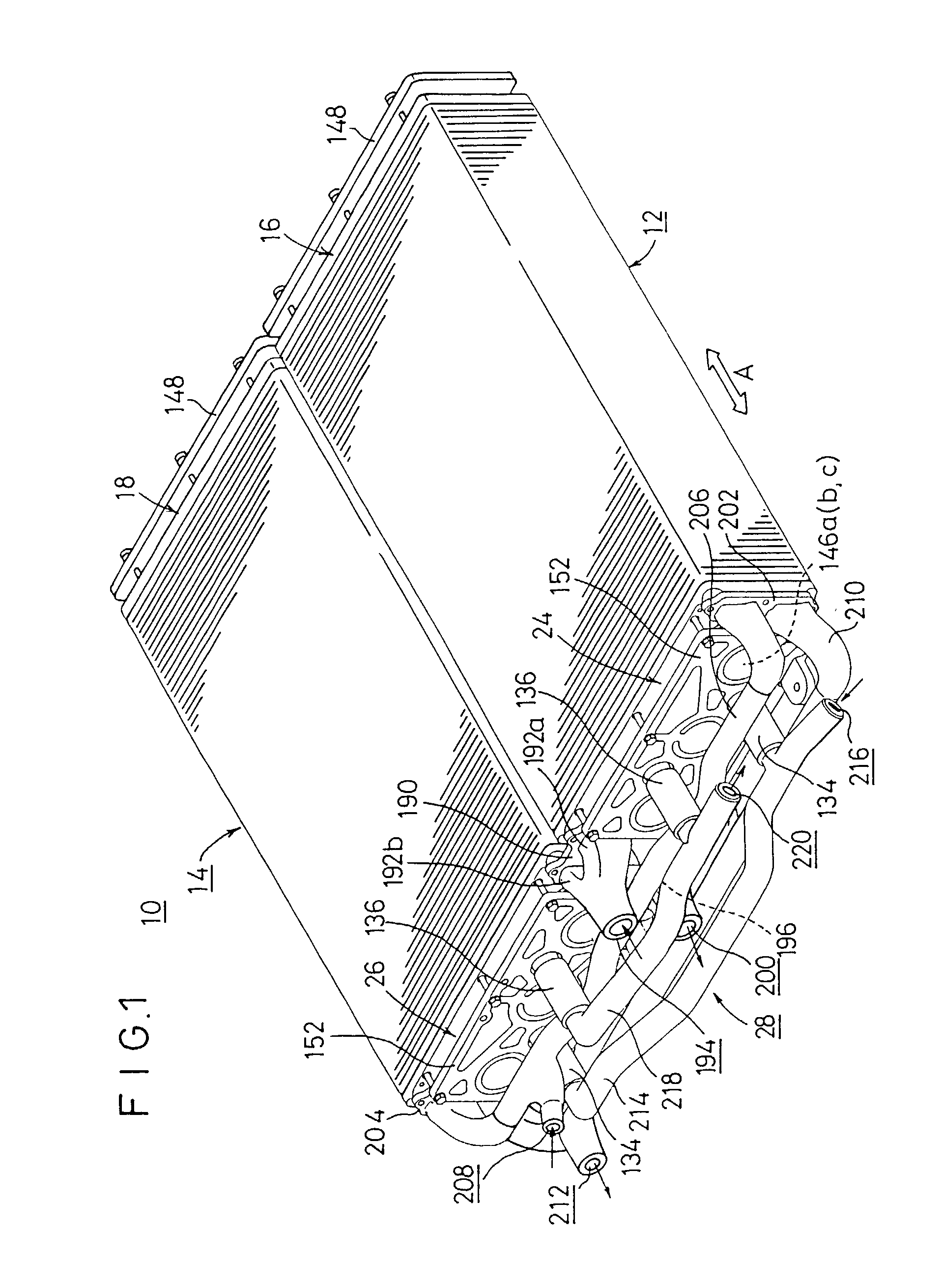
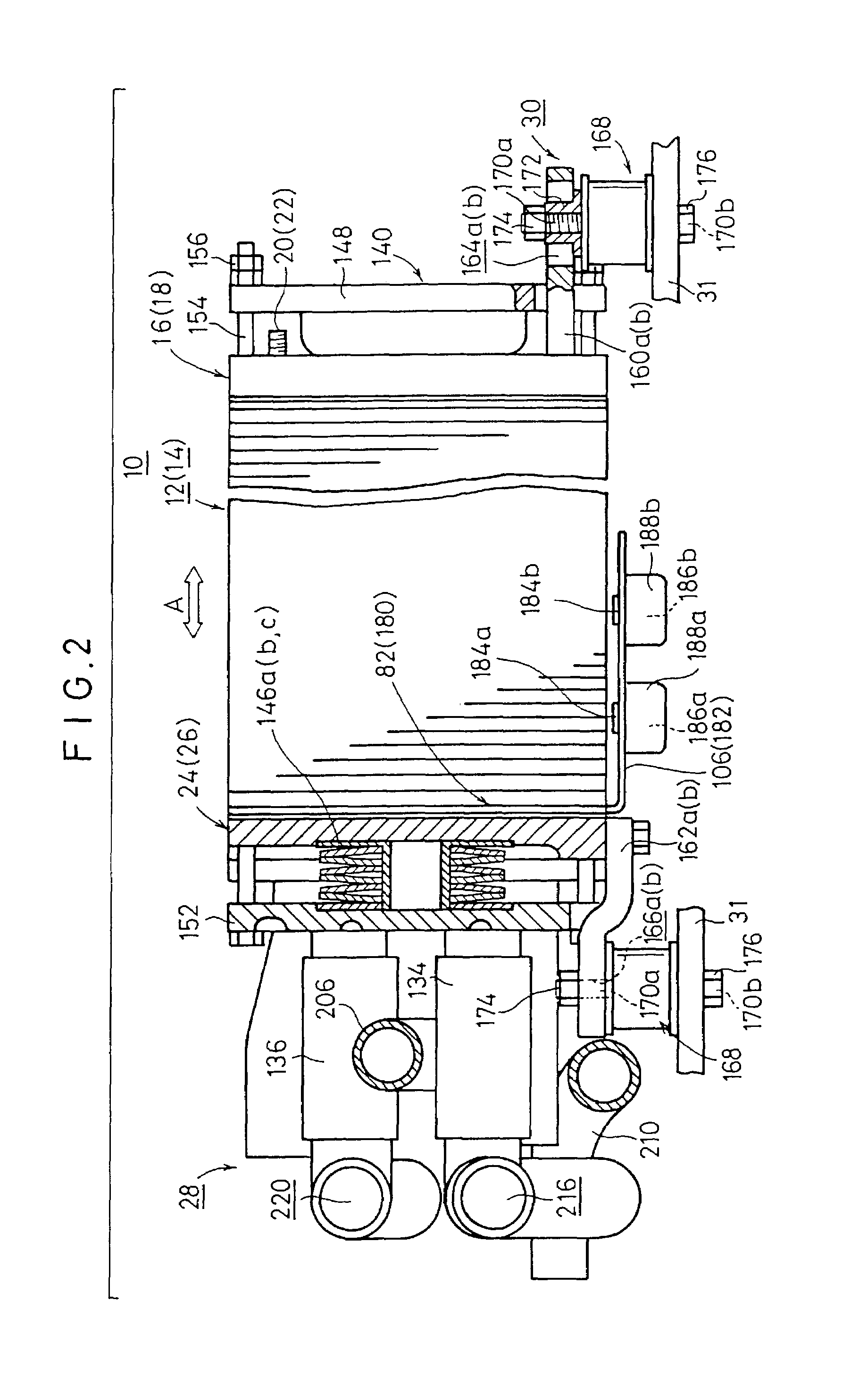
[0033]FIG. 1 shows a schematic perspective view illustrating a fuel cell system 10 according to an embodiment of the present invention, and FIG. 2 shows a side view illustrating the fuel cell system 10.

[0034]The fuel cell system 10 comprises a first fuel cell stack 12 and a second fuel cell stack 14 which are arranged in parallel to one another in the horizontal direction (direction of the arrow A). A first electric power-deriving terminal 20 as a positive electrode, and a second electric power-deriving terminal 22 as a negative electrode are provided on first end plates 16, 18 which constitute vertical surfaces disposed at first ends on an identical side of the first and second fuel cell stacks 12, 14 respectively.

[0035]A piping mechanism 28, which is used to supply and discharge a fuel gas, an oxygen-containing gas, and a cooling medium with respect to the first and second fuel cell stacks 12, 14, is incorporated on a side of second end plates 24, 26 which constitute vertical surf...


PUM


Abstract

A fuel cell system comprises first and second parallel fuel cell stacks (12, 14) in which a positive electrode and a negative electrode of adjoining terminal electrodes are set to be opposite to one another. First and second conductive plates (82, 180) are incorporated at ends on an identical side of the first and second fuel cell stacks (12, 14). First and second connecting plate sections (106, 182) extend from the first and second conductive plates (82, 180) closely to one another under the first and second fuel cell stacks (12, 14). The first and second connecting plate sections (106, 182) are electrically connected by flexible strand wires (186a, 186b). Accordingly, the fuel cell system reliably avoids stress caused by vibration or the like at a connecting portion for electrically connecting the first and second fuel cell stacks (12, 14) to one another.

Description

RELATED APPLICATIONS[0001]The present application is a continuation-in-part of U.S. patent application Ser. No. 09 / 634,100, filed Aug. 8, 2000, now U.S. Pat. No. 6,455,179, the contents of which are herein incorporated by reference.BACKGROUND OF THE INVENTION[0002]1. Field of the Invention[0003]The present invention relates to a vehicle-carried type fuel cell system provided with fuel cell stacks each comprising a plurality of fuel cell units each composed of a solid polymer ion exchange membrane interposed between an anode electrode and a cathode electrode, the plurality of fuel cell units being stacked in the horizontal direction with separators intervening therebetween.[0004]2. Description of the Related Art[0005]For example, the solid polymer type fuel cell comprises a fuel cell unit including an anode electrode and a cathode electrode disposed opposingly on both sides of an ion exchange membrane composed of a polymer ion exchange membrane (cation exchange membrane) respectively...

Claims


Application Information

Patent Timeline
IPC IPC(8): H01M2/02H01M8/02H01M8/24
CPCH01M8/249H01M8/0202Y02E60/50H01M2300/0082
Inventor SUGITA, NARUTOSHIOSAO, NORIAKIUSHIO, TAKESHI
Owner HONDA MOTOR CO LTD
Why Eureka
Eureka Blog
Learn More