Electrically-coupled micro-electro-mechanical filter systems and methods

a micro-electromechanical filter and electrical coupling technology, applied in the direction of coupling parts mounting, coupling device connection, electrical apparatus, etc., can solve the problems of mechanical coupling techniques that can present obstacles to performance in some applications, and the size and cost of advanced consumer electronics such as miniature radios and wristwatches

Inactive Publication Date: 2006-08-29
GEORGIA TECH RES CORP
View PDF17 Cites 19 Cited by
  • Summary
  • Abstract
  • Description
  • Claims
  • Application Information

AI Technical Summary

Problems solved by technology

Advanced consumer electronics such as miniature radios and wristwatch cellular phones pose severe limitations on the size and cost of frequency selective units (e.g., frequency references and filters) contained therein.
Mechanical coupling techniques can present obstacles to performance in some applications.

Method used


Image

  • Electrically-coupled micro-electro-mechanical filter systems and methods
  • Electrically-coupled micro-electro-mechanical filter systems and methods
  • Electrically-coupled micro-electro-mechanical filter systems and methods

Examples


Embodiment Construction

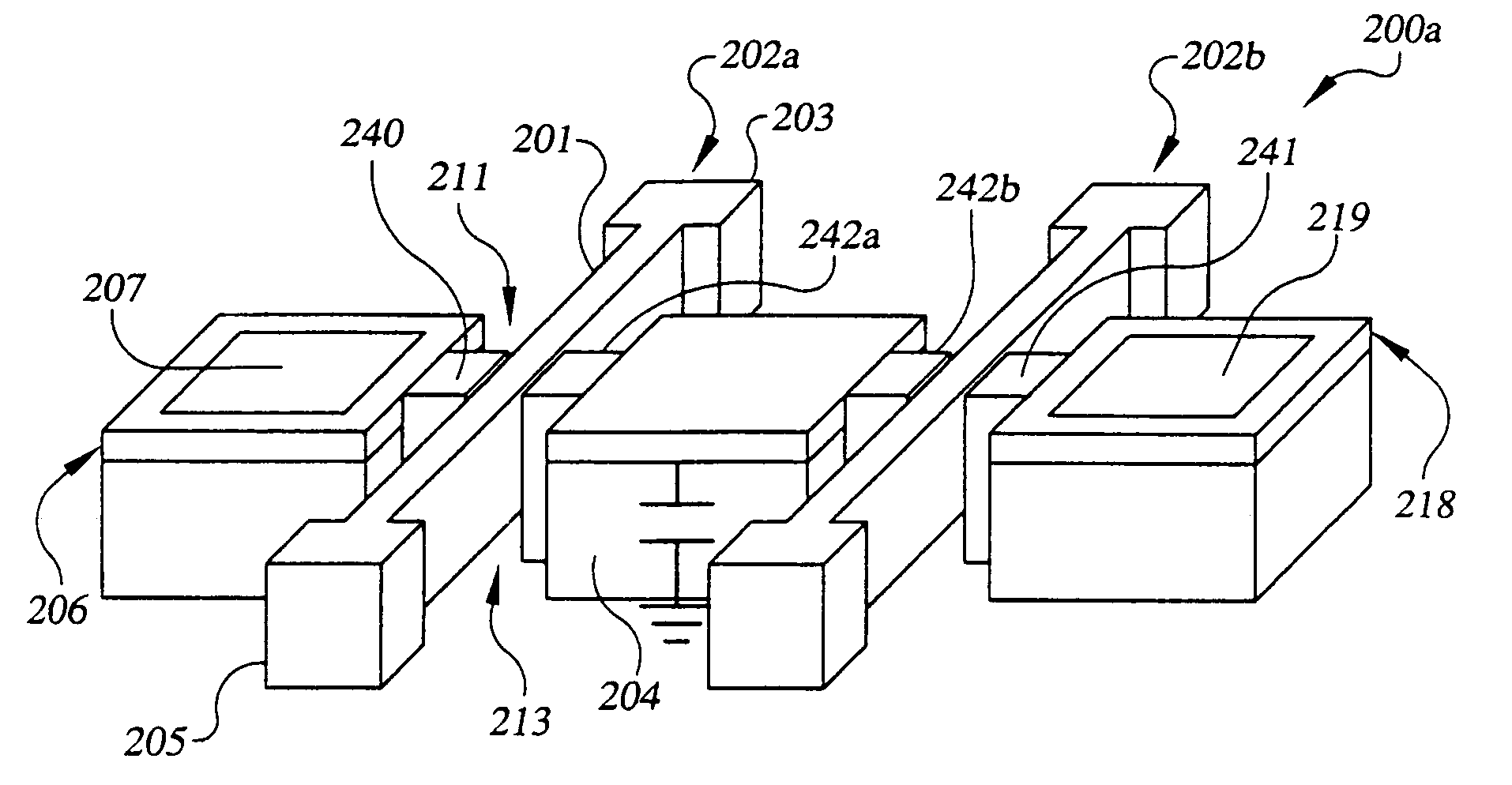
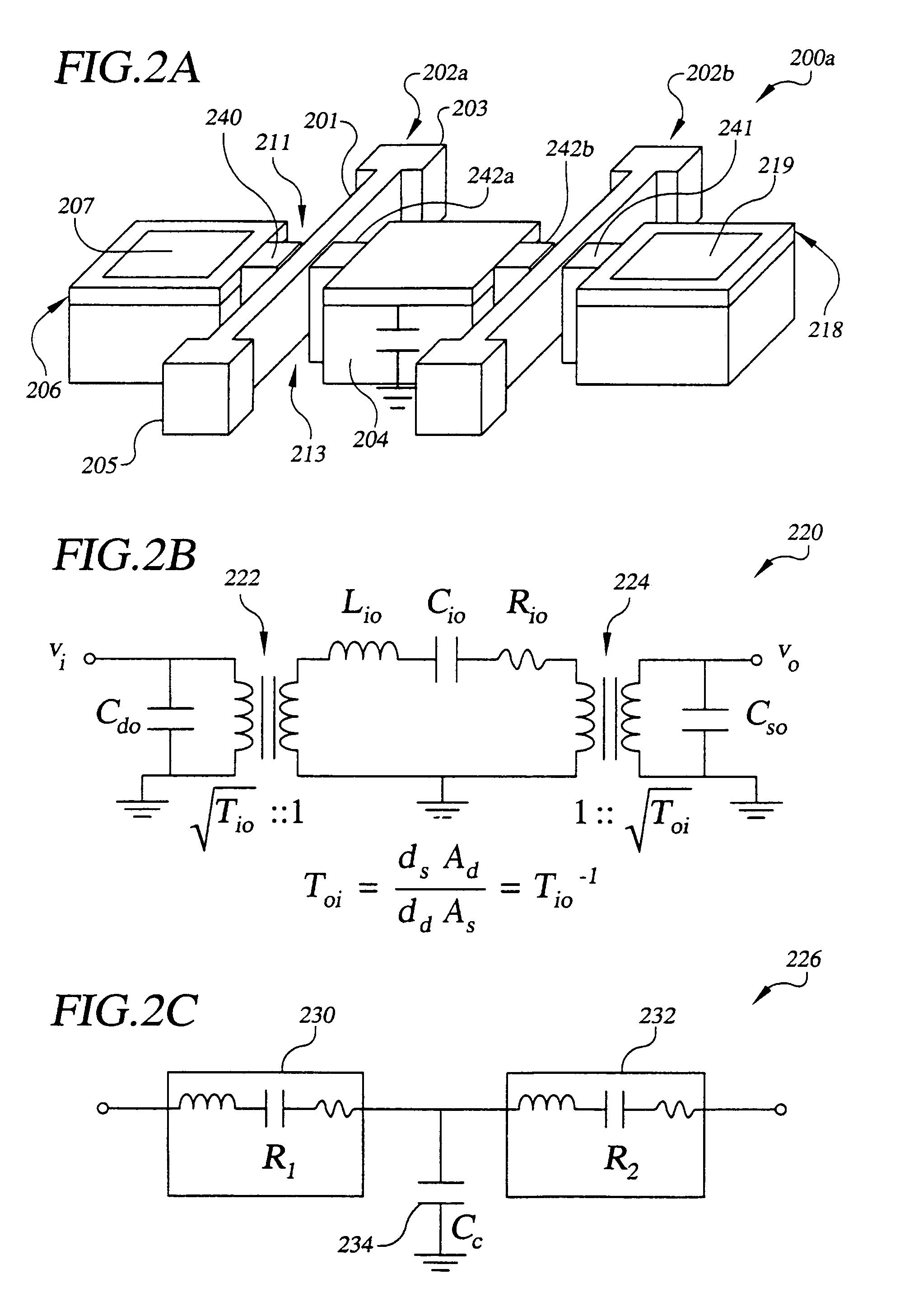
[0030]Preferred embodiments of electrically-coupled MEMS (micro-electro-mechanical systems) resonator filter systems and methods are disclosed. In particular, filter synthesis methods and systems derived thereof are disclosed. The filter synthesis methods provide a technique for electrically coupling high quality factor (Q), single-crystal silicon MEMS resonators. Q can generally be described as a measure of energy stored in a system divided by the energy dissipated in the system. Q can be characterized in terms of frequency response of a resonator, such as the ratio of the center frequency (f0) to the 3-dB (decibel) bandwidth of the resonator device. The filter synthesis methods simplify the implementation of MEMS filter design, fabrication, and / or frequency scaling. For example, the filter synthesis methods do not require mechanical design expertise to implement, and can be designed by electrical engineers using available circuit simulation techniques (e.g., SPICE). In addition, e...


PUM


Abstract

An electrically-coupled micro-electro-mechanical system (MEMS) filter system and method are disclosed. In one embodiment, the MEMS filter system comprises a first microelectromechanical system (MEMS) resonator comprising a first resonating element, a second MEMS resonator comprising a second resonating element, the sescond resonating element closely spaced and mechanically separate from the first resonating element, wherein the first MEMS resonator is coupled to the second MEMS resonator through the electrostatic force acting between resonating portions of the MEMS resonators, and additional MEMS resonators electrically coupled to the first MEMS resonator, the second MEMS resonator, or the first and second MEMS resonators.

Description

CROSS-REFERENCE TO RELATED APPLICATION[0001]This application claims the benefit of U.S. Provisional Application No. 60 / 412,721, filed Sep. 23, 2002, which is entirely incorporated herein by reference.[0002]This application is related to copending U.S Utility patent application entitled “Capacitive Resonators and Methods of Fabrication,” having Ser. No. 10 / 632,176, filed on the Jul. 31, 2003, which is entirely incorporated herein by reference.STATEMENT REGARDING FEDERALLY SPONSORED RESEARCH OR DEVELOPMENT[0003]The U.S. government has a paid-up license in this invention and the right in limited circumstances to require the patent owner to license others on reasonable terms as provided for by the terms of Contract No. DAAH01-01-1-R004 awarded by the U.S. Army.TECHNICAL FIELD[0004]The present invention is generally related to MEMS (micro-electro-mechanical systems) technology, and, more particularly, is related to MEMS filter systems and methods.BACKGROUND OF THE INVENTION[0005]Advanced...

Claims


Application Information

Patent Timeline
Patent Type & Authority Patents(United States)
IPC IPC(8): H03H9/00H03H9/205H03H9/46H03H9/52
CPCH03H9/02H03H9/525H03H9/462H03H2009/02496H03H9/02244
Inventor AVAZI, FARROKHANARAKI, SIAVASH POURKAMALI
Owner GEORGIA TECH RES CORP
Why Eureka
Try Eureka