MEMS device for an adaptive optics mirror

a mirror and optics technology, applied in the field of microelectromechanical systems, can solve the problems of significantly reducing the fill factor, difficult or even impossible to meet, and reducing the image quality, so as to achieve small lateral displacement and small surface area

Active Publication Date: 2006-08-29
LUCENT TECH INC
View PDF12 Cites 42 Cited by
  • Summary
  • Abstract
  • Description
  • Claims
  • Application Information

AI Technical Summary

Benefits of technology

[0009]In one embodiment of the invention, the motion actuator has a movable electrode, on which the mirror pixel is mounted. The movable electrode is supported on the substrate by a pair of upright springs, each having two parallel segments joined at one end of the spring and disjoint at the other end. One disjoint segment end is coupled to the substrate, while the other disjoint segment end is coupled to the movable electrode. The end of the upright spring corresponding to the joined segment ends points away from the substrate such that (i) the spring body protrudes through a narrow slot in the mirror pixel and (ii) the mirror plane lies at about the mid-point of the upright spring. Advantageously, a mirror pixel implemented in accordance with an embodiment of the invention has a relatively small lateral displacement during rotation while the mirror support structure takes up a relatively small surface area within the mirror plane. This enables implementation of a segmented mirror with tightly spaced mirror pixels providing a fill factor higher than about 98%.

Problems solved by technology

The cumulative effect of these changes along the beam propagation path may lead to beam wandering, spreading, and intensity fluctuations, each of which degrades image quality.
However, for many prior-art designs, these requirements are in direct conflict with each other and therefore difficult or even impossible to meet.
The latter, however, significantly reduces the fill factor.

Method used


Image

  • MEMS device for an adaptive optics mirror
  • MEMS device for an adaptive optics mirror
  • MEMS device for an adaptive optics mirror

Examples


Embodiment Construction

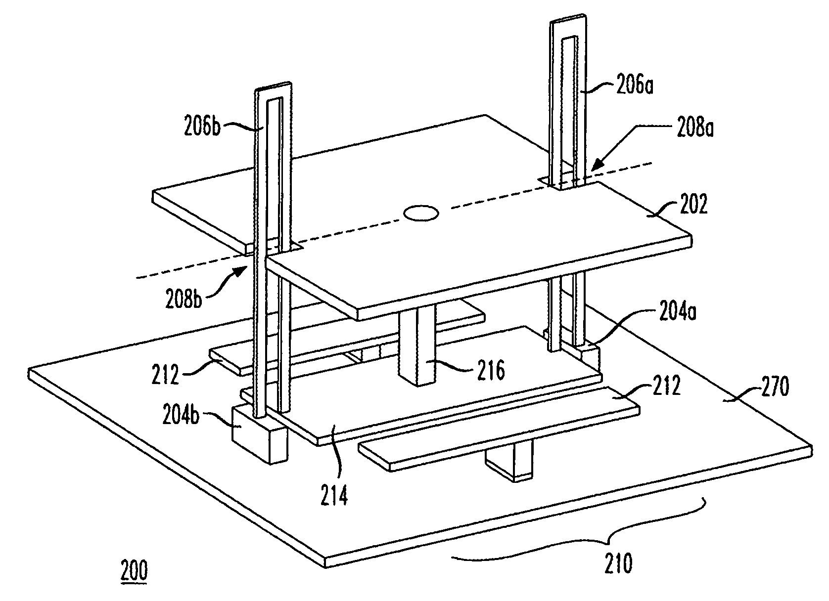
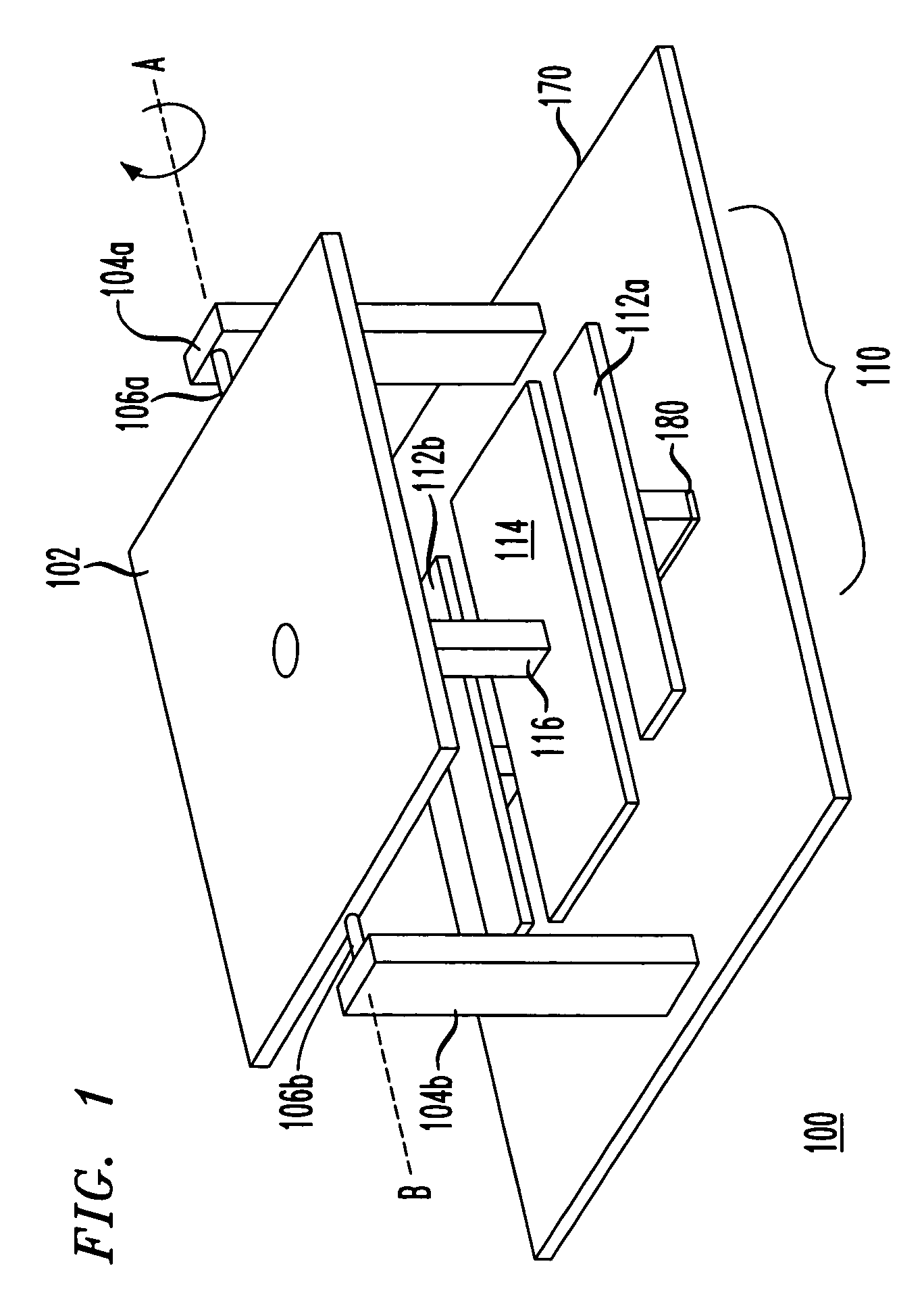
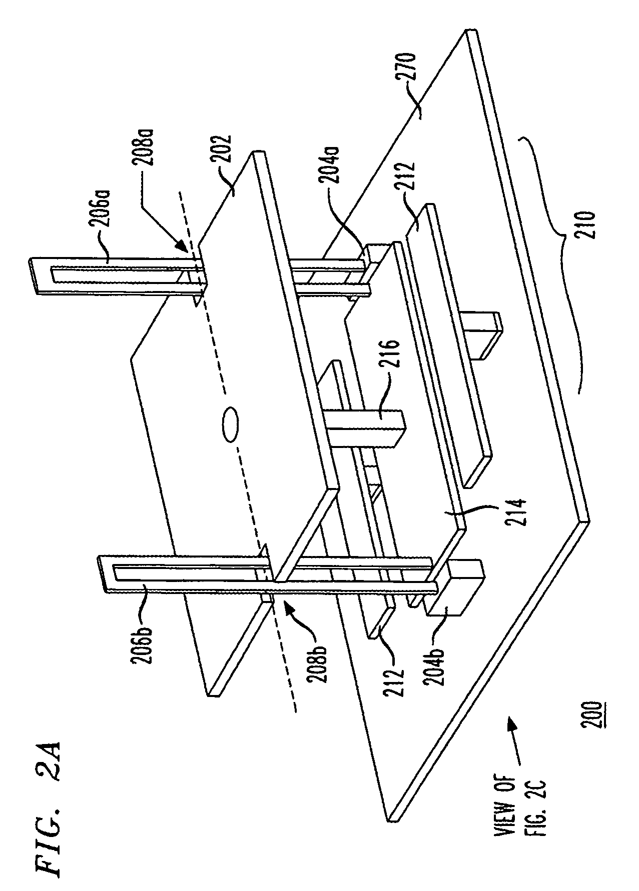
[0016]FIG. 1 shows a three-dimensional perspective view of an exemplary MEMS device 100 arranged in accordance with the principles of the invention, which may be used to implement a pixel of an adaptive optics mirror. Device 100 has a movable plate 102 and connected to a motion actuator 110. Plate 102 is supported by a pair of torsion rods 106a–b, each connected between the plate and one of posts 104a–b attached to a substrate 170. Rods 106a–b define an axis of rotation for plate 102 shown by the dashed line and labeled AB in FIG. 1.

[0017]Actuator 110 is a fringe-field actuator made up of two lateral electrodes 112a–b and an intermediate electrode 114. Lateral electrodes 112a–b are attached to substrate 170 and, as such, are stationary. In contrast, intermediate electrode 114 is attached to plate 102 by a link rod 116 and, as such, is movable, together with the plate, with respect to substrate 170. When intermediate electrode 114 is moved toward one of lateral electrodes 112, link r...


PUM

PropertyMeasurementUnit
temperatureaaaaaaaaaa
circumferenceaaaaaaaaaa
distanceaaaaaaaaaa

Abstract

A MEMS device having a movable mirror pixel supported on a substrate and coupled to a motion actuator so as to enable rotation of the mirror pixel about an axis lying within the mirror plane. In one embodiment, the motion actuator has a movable electrode, on which the mirror pixel is mounted. The movable electrode is supported on the substrate by a pair of upright springs, each having two parallel segments joined at one end and disjoint at the other end. One disjoint segment end is coupled to the substrate, while the other disjoint segment end is coupled to the movable electrode. The end of the upright spring corresponding to the joined segment ends points away from the substrate such that (i) the spring body protrudes through a narrow slot in the mirror pixel and (ii) the mirror plane lies at about the mid-point of the spring.

Description

CROSS-REFERENCE TO RELATED APPLICATION[0001]The subject matter of this application is related to that of U.S. patent application Ser. No. 10 / 772,847, filed Feb. 5, 2004, which is incorporated herein by reference.BACKGROUND OF THE INVENTION[0002]1. Field of the Invention[0003]The present invention relates to adaptive optics and, more specifically, to micro-electromechanical systems (MEMS) for implementing adaptive optics.[0004]2. Description of the Related Art[0005]Adaptive optics is a field of optics dedicated to the improvement of optical signals using information about signal distortions introduced by the environment in which the optical signals propagate. An excellent introductory text on the subject is given in “Principles of Adaptive Optics” by R. K. Tyson, Academic Press, San Diego, 1991, the teachings of which are incorporated herein by reference.[0006]A representative example of an adaptive optical element is a deformable mirror driven by a wavefront sensor and configured to...

Claims


Application Information

Patent Timeline
Patent Type & Authority Patents(United States)
IPC IPC(8): G02B26/00B81B3/00G02B26/02G02B26/08G02F1/03G02F1/07H02N1/10
CPCG02B26/0841
Inventor GREYWALL, DENNIS S.
Owner LUCENT TECH INC
Why Eureka
Try Eureka