Distribution unit and electric connection box including the same

a technology of distribution unit and electric connection box, which is applied in the direction of substation/switching arrangement casing, electrical equipment casing/cabinet/drawer, lighting and heating equipment, etc., can solve the fear of short circuit between the external connection terminals, the creepage distance of each external connection terminal is shortened, and the effect of suppressing the effect of the power circuit section

Active Publication Date: 2006-08-29
AUTONETWORKS TECH LTD +2
View PDF15 Cites 60 Cited by
  • Summary
  • Abstract
  • Description
  • Claims
  • Application Information

AI Technical Summary

Benefits of technology

[0026]According to the invention, the power circuit section includes the external connection terminals each having the upright part rising from the circuit disposition face of the heat radiation member and the extension part extending from the tip of the upright part to the outside of the circuit disposition face roughly in parallel with the circuit disposition face. Thus, to join an external terminal to the external connection terminal from the direction roughly parallel with the circuit disposition face, the extension part can be placed at a distance from the heat radiation member in the presence of the upright part and a short circuit in the extension part of the external connection terminal can be prevented reliably. The deflection regulation part is provided for abutting the upright part for regulating deflection on the opposite side to the extension direction of the extension part, so that deflection of the upright part caused by the external force (insertion force) acting on the extension part at the connecting time with a different external terminal can be regulated. That is, the external force (insertion force) acting on the extension part at the connecting time with the different external terminal can be substantially supported on the deflection regulation part. Therefore, the external force does not propagate to the power circuit section, the bus bar does not become deformed, and a gap is not formed between the power circuit section and the heat radiation member. If the different external terminal is joined to the external connection terminal from the direction roughly parallel with the circuit disposition face, the effect on the power circuit section can be suppressed. Moreover, deflection of the upright part is regulated, so that a situation in which deflection of the upright part causes the extension part to drop into the case can be circumvented reliably.
[0027]According to a ninth aspect of the invention, in the distribution unit as in the eighth aspect, the deflection regulation part is provided integrally with the case. In doing so, the external force acting on the extension part at the connecting time with a different external terminal can be distributed to the case, the durability of the deflection regulation part can be improved, and moreover the deflection regulation part can be placed at any desired position simply by assembling the case; the placement step of the deflection regulation part can be thus skipped for improving the manufacturing efficiency.

Problems solved by technology

Therefore, it is considered that the power distributor is made more compact for miniaturizing the electric connection box; however, miniaturization of the power distributor involves certain limits.
In the state in which the external connection terminals are densely placed, the creepage distance for insulation of each external connection terminal is shortened and there is the fear of a short circuit between the external connection terminals.
It is difficult to furthermore miniaturize the power distributor, particularly the power distributor provided with a plurality of terminal assemblies.
In the structure, however, the joining direction is limited to the direction of the normal to the circuit disposition face.
In this case, the insertion force at the connecting time with a different external terminal propagates directly to the power circuit section along the length direction of the external connection terminal and thus it is feared that the bus bar in the power circuit section may become deformed or that if the power circuit section is bonded to a heat radiation member, the bond face may peel off, etc., and by extension it is feared that a gap may be formed between the power circuit section and the heat radiation member, degrading the heat conduction efficiency.

Method used


Image

  • Distribution unit and electric connection box including the same
  • Distribution unit and electric connection box including the same
  • Distribution unit and electric connection box including the same

Examples


first embodiment

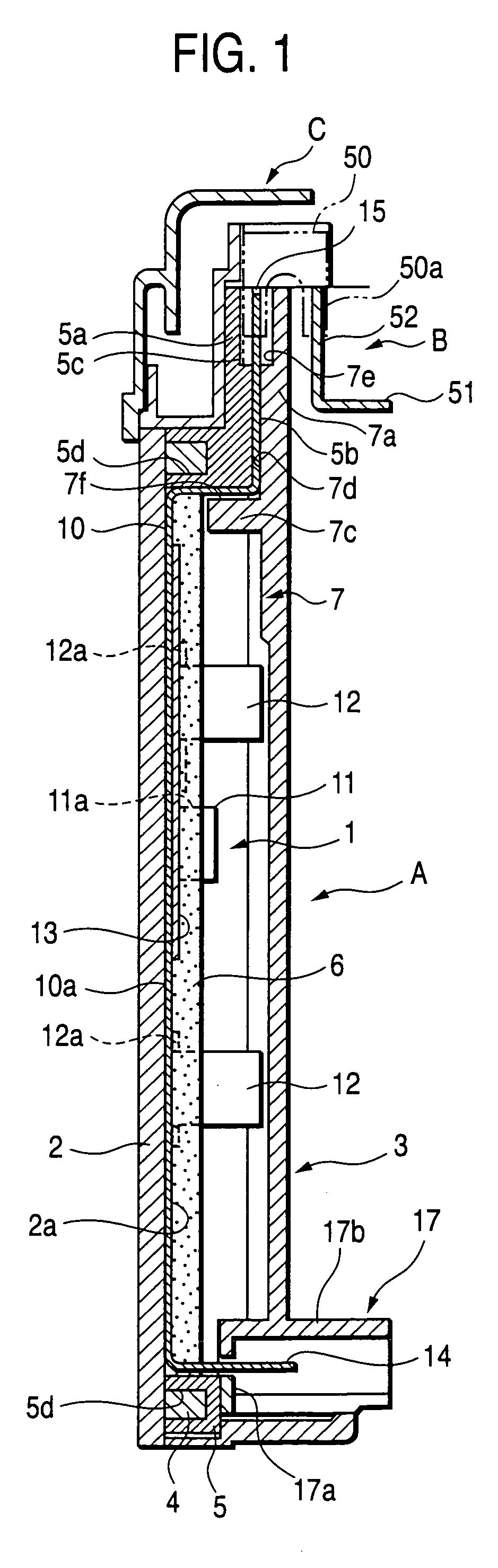
[0042]A distribution unit according to a first embodiment of the invention is provided mainly for preventing a short circuit between fuse connection terminals.

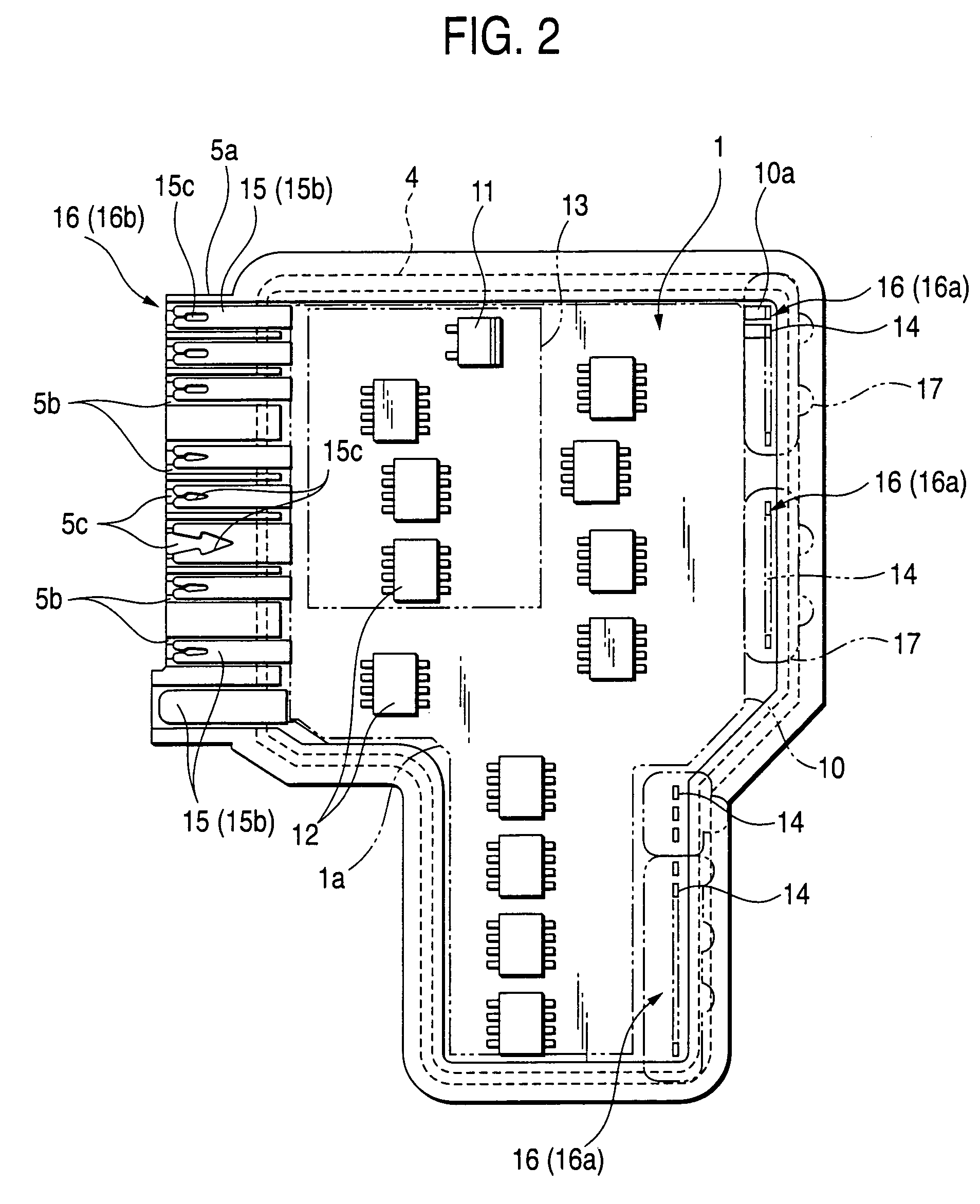
[0043]FIG. 1 is a sectional view to show the distribution unit of the first embodiment in a state in which the distribution unit is joined to bus bar boards (some not shown) by fuse elements. FIG. 2 is a plan view to show the distribution unit in a state in which a power circuit section of the distribution unit is housed in a lower case of an insulating case (described later).

[0044]The distribution unit A is housed in an electric connection box not shown in the figure vertically, namely, is housed with the upper part in FIG. 1 upward in the first embodiment, but the placement direction of the distribution unit A is not limited to it; for example, the distribution unit A may be placed horizontally. In the description to follow, the directions when the distribution unit A is placed vertically may be used for convenience to ident...

second embodiment

[0082]A distribution unit according to a second embodiment of the invention is provided entirely for preventing a short circuit between connector connection terminals.

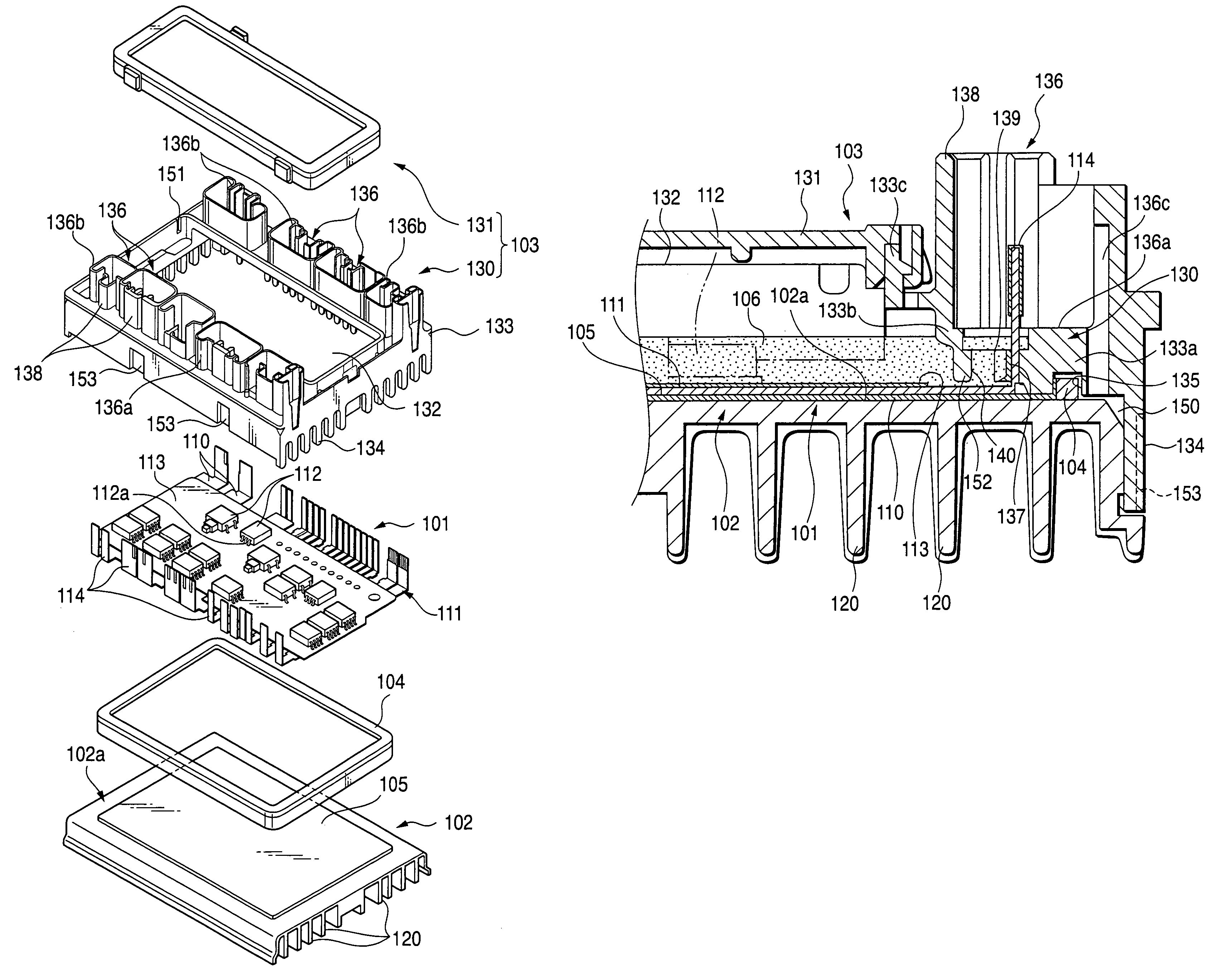
[0083]FIG. 5 is an exploded perspective view to show the distribution unit according to the second embodiment. The distribution unit includes a power circuit section 101 containing a plurality of bus bars 110, a heat radiation member 102 on which the power circuit section 101 is disposed via an insulating layer 105, and a case 103 to cover the power circuit section 101. As shown in FIG. 7, the case 103 and the heat radiation member 102 are joined to each other with a resin seal member 104 provided in the case 103 sandwiched between the case 103 and the heat radiation member 102 and in this state, a water resistance resin is filled to form a water resistance layer 106.

[0084]The power circuit section 101 includes a bus bar implementation board 111 having a plurality of bus bars 110 arranged in an area shaped like a prede...


PUM


Abstract

A distribution unit has a power circuit section including a plurality of bus bars with electronic parts mounted on at least some of the bus bars. Ends of specific bus bars are projected from a main body section of the power circuit section in a adjacent manner to form fuse connection terminals. Each of the fuse connection terminals has a tip placement part to place a fuse terminal. An insulating case made of an insulating material for covering the power circuit section is opened in the projection direction of the fuse connection terminals to enable the fuse terminal to be placed in the tip placement part of the fuse connection terminal from the outside of the insulating case. The insulating case has a short-circuit prevention section intervening between the fuse connection terminals for preventing a short circuit between the fuse connection terminals.

Description

BACKGROUND OF THE INVENTION[0001]1. Field of the Invention[0002]This invention relates to a distribution unit for implementing a power circuit section for distributing power to a plurality of electronic units from a vehicle-installed power supply in a vehicle, such as an automobile, and an electric connection box including the distribution unit.[0003]2. Description of the Related Art[0004]Hitherto, an electric connection box containing fuses and relay switches built in a power circuit section provided by stacking a plurality of bus bar boards as means for distributing power to each electronic unit from a common vehicle-installed power supply has been known.[0005]By the way, in recent years, a power distributor as a distribution unit having semiconductor switching elements such as FETs in place of or together with the relay switches, interposed between input and output terminals has been developed to accomplish miniaturization of the electric connection box and high-speed switching c...

Claims


Application Information

Patent Timeline
Patent Type & Authority Patents(United States)
IPC IPC(8): H05K7/20B60R16/02B60R16/023H05K5/00H05K5/06H05K7/02
CPCB60R16/0238H05K7/026H05K5/0069H05K5/0056B60R16/0239H05K5/062H05K7/02H05K7/20854H05K7/209
Inventor KOBAYASHI, TAKEHITOYAMANE, SHIGEKIONIZUKA, TAKAHIRO
Owner AUTONETWORKS TECH LTD
Why Eureka
Try Eureka