
System for providing fabric activity switch control in a communications system

a technology of communication system and activity switch, which is applied in the field of system for providing fabric redundancy and activity switch control in a communications system, can solve the problems of not meeting industry standards for certain switching applications, affecting the operation of fabric activity switch, and prior art designs showing some inherent limitations

Inactive Publication Date: 2006-08-29
WSOU INVESTMENTS LLC +1
View PDF7 Cites 23 Cited by
  • Summary
  • Abstract
  • Description
  • Claims
  • Application Information

AI Technical Summary

Benefits of technology

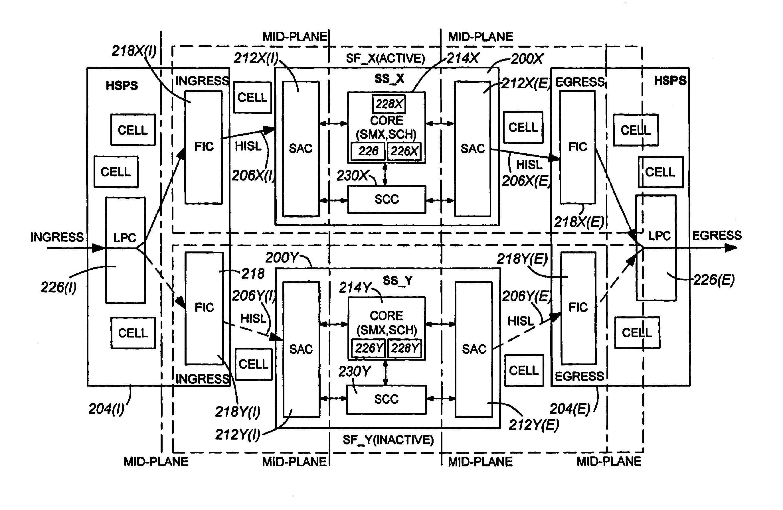
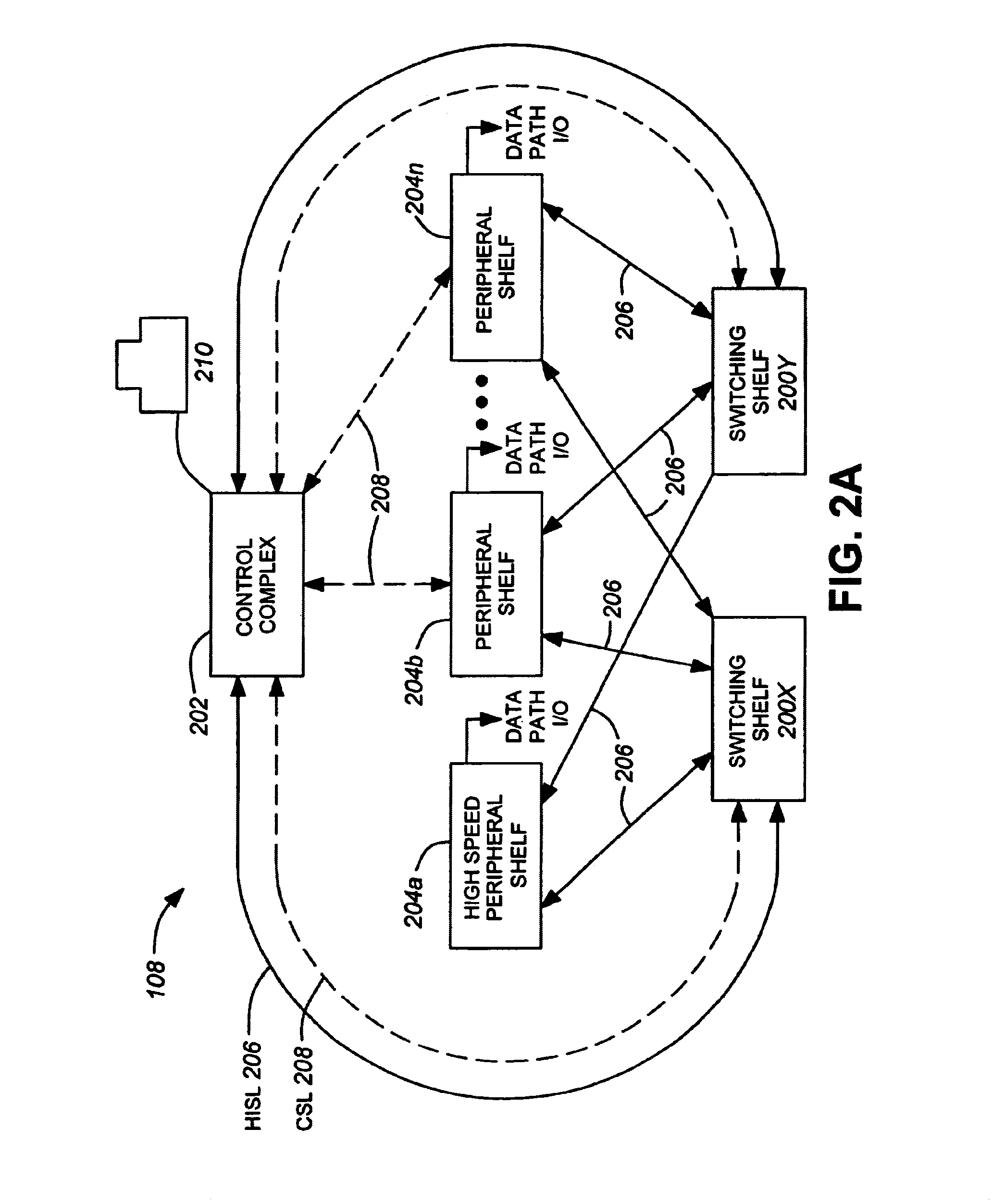
[0006]In order to overcome the limitations in the prior art, the present invention provides activity switch control functions on a control plane which are separate and independent of data switching functions on a data plane. Separation of the control plane and data plane in accordance with the present invention allows a robust, distributed architecture, capable of providing redundancy both within the data plane and within the control plane. Furthermore, the separate and independent control plane and a hardware-centric switching implementation allows significantly improved fabric activity switchover times in comparison to prior art software-centric implementations.
[0020]According to another aspect of the invention, there is provided a fabric activity switch circuit for a communications switch, the communications switch including at least one input / output (“I / O”) device coupled to each of first and second switching fabrics, the circuit comprising: a first interface for receiving first and second I / O status signals from the at least one I / O device, the first and second I / O status signals being indicative of respective faults in the first and second switching fabrics and being generated by respective monitors provided in the at least one I / O device; a second interface for receiving first and second fabric status signals from the first and second switching fabrics, respectively, the first and second fabric status signals being indicative of respective faults in the first and second switching fabrics and being generated by respective monitors provided in the first and second switching fabrics; gates coupled to the first and second interfaces for generating an output signal for selecting the first switching fabric as an active switching fabric if a combination of the second I / O and fabric status signals indicate a fault in the second switching fabric and for selecting the second switching fabric as the active switching fabric if a combination of the first I / O and fabric status signals indicate a fault in the first switching fabric. The fabric activity switch circuit may further include a third interface coupled to the gates for transmitting the output signal to a fabric switch for switching between the first and second switching fabrics. The fabric activity switch circuit may further include redundant gates and redundant first, second, and third interfaces to improve reliability. The fabric activity switch circuit may further include a fourth interface, coupled to the gates, for receiving at least one of an override signal for overriding the selecting of the active switching fabric and a select signal for directing the selecting of the active switching fabric. In the fabric activity switch circuit, at least one of the override and select signals may be provided by a control terminal. And, the switching between the first and second switching fabrics may occur in under 60 milliseconds.

Problems solved by technology

Prior art designs exhibit some inherent limitations.
This co-dependency between the redundant fabrics may be problematic, depending on the type of fault that is initiating the activity switch between the fabrics.
Furthermore, in prior art designs, the time it takes to execute an activity switch between redundant fabrics may be in the order of several seconds or more, which may not comply with industry standards for certain switching applications.
Many prior art designs do not meet this Bellcore standard for an activity switch upon a first fault.

Method used


Image

  • System for providing fabric activity switch control in a communications system
  • System for providing fabric activity switch control in a communications system
  • System for providing fabric activity switch control in a communications system

Examples


Embodiment Construction

[0041]The description which follows, and the embodiments described therein, are provided by way of illustration of an example, or examples, of particular embodiments of the principles of the present invention. These examples are provided for the purposes of explanation, and not limitation, of those principles and of the invention. In the description, which follows, like parts are marked throughout the specification and the drawings with the same respective reference numerals.

[0042]The terms as used in this description have the definitions as set out in Table A, below. Trade marks are specified.

[0043]

TABLE ATermDefinitionATMAsynchronous Transfer ModeCCControl ComplexCICControl Interconnect CardCRCCyclic Redundancy CheckCSLControl Service LinkDFICDual Fabric Interface CardsFACFacilities Access CardFSMFinite State MachineFICFabric Interface CardFPGAField Programmable Gate ArrayGbpsGiga bits per secondHFICHigh Speed Fabric Interface CardHISLHigh Speed Inter Shelf LinkHSCHigh Speed Shelf...


PUM


Abstract

Disclosed is a system for providing redundancy on a communications switch platform having a data plane for processing data. The data plane includes an active fabric having an ingress and an egress and establishing a first datapath, a redundant fabric having an ingress and an egress and establishing a second datapath, and a fabric switch for aligning the egress of one of said fabrics to a system output. A separate and independent control plane is provided for monitoring the processing of data. The control plane includes: (i) a plurality of monitors operatively connected to monitor the status of the active and redundant fabrics in the data plane for a fault; and (ii) a fabric activity switch circuit adapted to determine whether the fault occurred in the active fabric in the data plane, and if so, to generate a fabric activity switch signal directed to said fabric switch in the data plane.

Description

FIELD OF THE INVENTION[0001]The invention relates to a system for providing fabric redundancy and activity switch control in a communications system, in particular in a routing switch platform.BACKGROUND OF INVENTION[0002]Many communication switch and router systems architectures provide redundant communications capabilities. Redundancy in a router system can be provided on two levels A first level provides redundancy within a single shelf for a communications switch. Therein, two or more modules provide redundant communications capabilities for another communication module on the same shelf. A second type of redundancy provides fabric redundancy beyond the switch matrix (SMX) cards and includes fabric interface cards (FICs) installed on input / output (I / O) shelves, high-speed inter-shelf links (HISLs), cables connecting I / O shelves and switch access cards (SACs) installed in switching shelves.[0003]Prior art designs exhibit some inherent limitations. For example, in certain prior ar...

Claims


Application Information

Patent Timeline
Patent Type & Authority Patents(United States)
IPC IPC(8): H04L1/22H04L12/24H04L12/26H04Q3/545
CPCH04L12/2602H04L41/0663H04L43/00H04Q3/54558H04L43/06H04Q2213/13349H04Q2213/1302H04Q2213/1304H04Q2213/13167H04Q2213/13196
Inventor FRIESEN, LARRYSOETEMANS, JOSEPH
Owner WSOU INVESTMENTS LLC
Learn More