System and method for the transfer of an existing logical data link

a logical data link and transfer method technology, applied in the field of transfer methods of existing logical data links, can solve the problems of large items of electronic mail received which contain attachments in the format of pc applications (e.g. word), cannot be displayed on the subscriber terminal, and the renewal of connection establishment is in itself time-consuming, so as to reduce transmission bandwidth and minimize data loss

Inactive Publication Date: 2006-08-29
NOKIA SIEMENS NETWORKS GMBH & CO KG
View PDF11 Cites 2 Cited by
  • Summary
  • Abstract
  • Description
  • Claims
  • Application Information

AI Technical Summary

Benefits of technology

[0015]In still another aspect of the invention, the logical data link is transferred from a first analog subscriber terminal to a second analog subscriber terminal which is connected to the analog subscriber line of the first subscriber terminal, and when the logical data link is taken over the connection previously established by the first subscriber terminal between the subscriber line and the aforesaid switching center of the telecommunications network is maintained. By dispensing with a new establishment of a connection between the subscriber line and the switching center which is necessary for transferring the existing logical data link, above all resources in the network and time are saved, and repeated interactions of the subscriber, for example through repeated typing in of his password, are avoided.
[0016]Yet another aspect of the invention includes that after transmission of the message concerning the communication state, a suspension of data transmission on the data link is initiated by the first subscriber terminal and once the logical data link has been taken over the resumption of data transmission is initiated by the second subscriber terminal. This minimizes the loss of data which would normally lead to a repeated transmission of the lost data, resulting in reduced transmission bandwidth.

Problems solved by technology

However, large items of electronic mail received which contain, for example, attachments in the format of PC applications (e.g. Word) cannot be displayed on the subscriber terminal, e.g. TF, because of the relatively small display and the low memory capacity.
A procedure of this type is disadvantageous for at least the following reasons:The establishment of a further or a new data link requires renewed authorization of the user, for example by entering passwords, and the selection of the access computer to be dialed.The renewed connection establishment is in itself time-consuming since it is necessary to assign a new data network address (IP address) to the subscriber terminal (the personal computer in the example) for an Internet session, for which the so-called PPP (point-to-point) protocol is preferably used.

Method used


Image

  • System and method for the transfer of an existing logical data link
  • System and method for the transfer of an existing logical data link
  • System and method for the transfer of an existing logical data link

Examples


Embodiment Construction

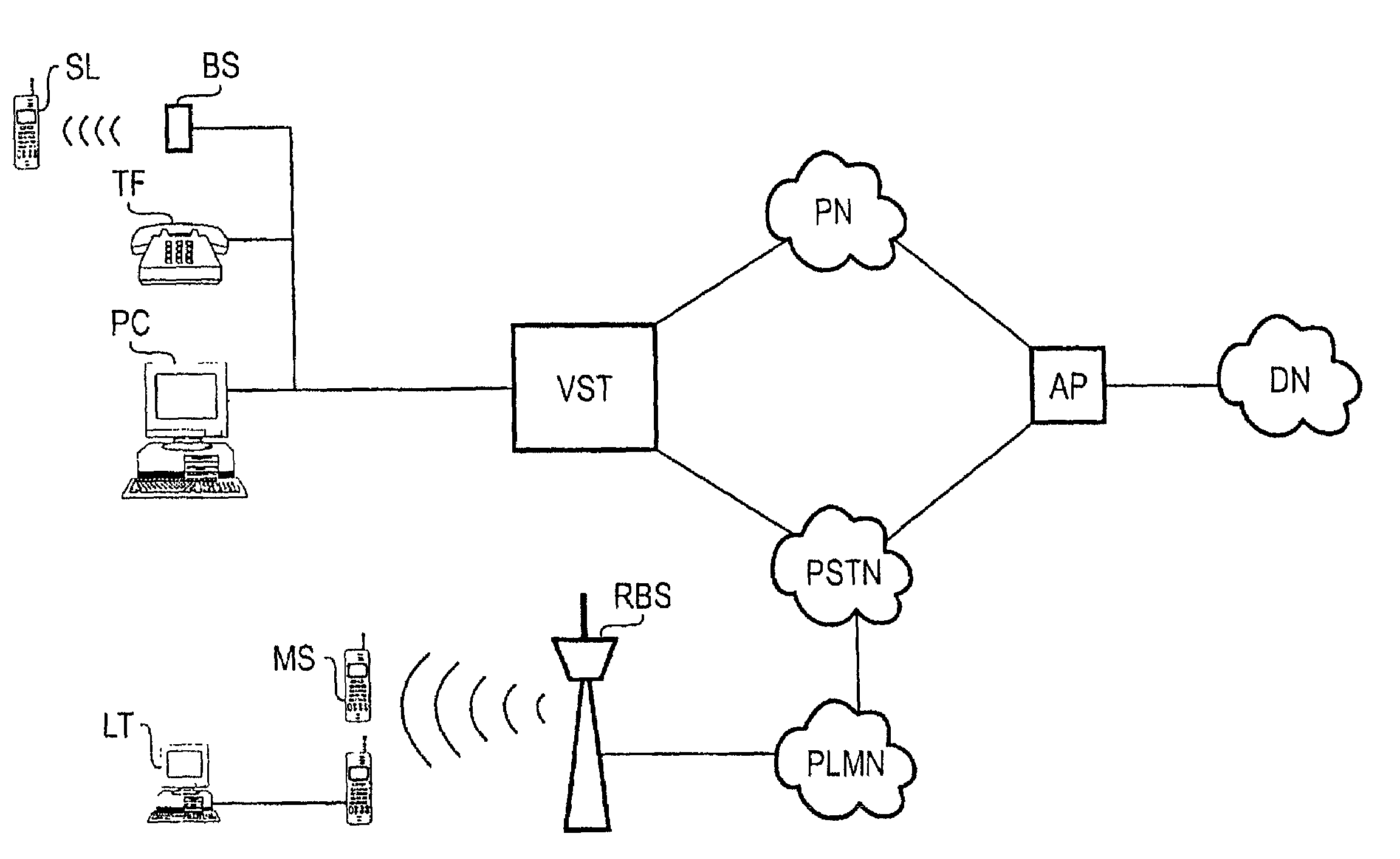
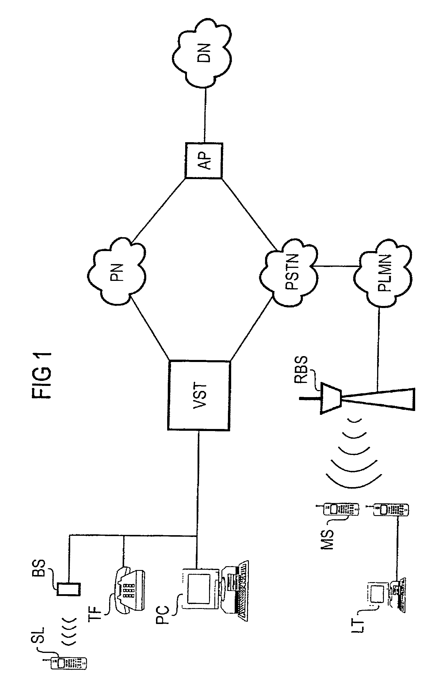
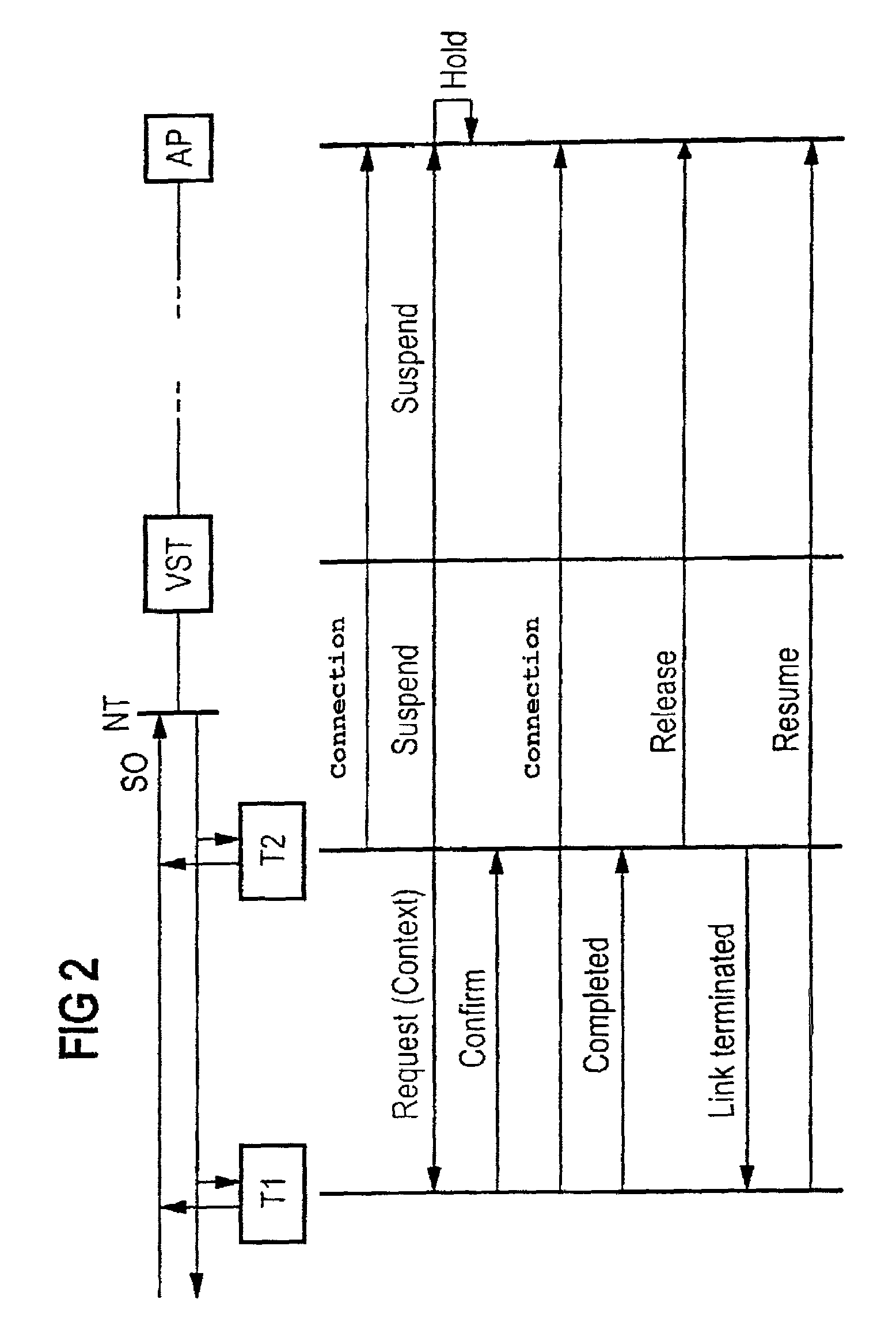
[0024]FIG. 2 represents an ISDN subscriber line in which the subscriber terminals, e.g. T1 and T2, are connected in parallel to a so-called S0 bus which terminates at the network termination NT schematically indicated in the figure. From the network termination NT, a subscriber line leads to the switching center VST of the public telephone network. The switching center has a connection to an access computer AP of a data network. The connection may be of various different types and is therefore indicated by a broken line in FIG. 2. For example, as described in FIG. 1, the connection may be established to the access computer AP via the public telephone network PSTN or via the No. 7 signaling network of the public telephone network, or via a packet-switched network, e.g. X.25. The access computer AP may also be integrated in the switching center VST. Various types of terminals are possible as subscriber terminals T1 and T2, e.g. a personal computer, a corded telephone with a display, o...


PUM


Abstract

An existing logical data link between a first subscriber terminal connected to a subscriber line of a telecommunications network and a switching center of the telecommunications network is transferred from a first subscriber terminal to a second subscriber terminal which is connected to the subscriber line of the first subscriber terminal or to another subscriber line of the second telecommunications network. The second subscriber terminal receives a message sent from the first subscriber terminal concerning the communication state of the existing logical data link and takes over this data link in the reported communication state, adapting its own state.

Description

CLAIM FOR PRIORITY[0001]This application claims priority to International Application No. PCT / DE00 / 002611 which was published in the German language on Aug. 4, 2000.TECHNICAL FIELD OF THE INVENTION[0002]The invention relates to a method for the transfer of an existing logical data link, and in particular, to a logical data link existing between a first subscriber terminal connected to a subscriber line of a telecommunications network and a switching center of the telecommunications network.BACKGROUND OF THE INVENTION[0003]A telecommunications network of this type is illustrated by way of example in FIG. 1. In FIG. 1, the telecommunications network is connected to an access computer AP of a data network DN, e.g. the Internet. Various subscriber terminals, e.g. a personal computer PC, a corded telephone TF and a cordless handset SL with its base station BS, are connected to a switching center VST. The switching center has a connection to the access computer AP of the data network DN v...

Claims


Application Information

Patent Timeline
Patent Type & Authority Patents(United States)
IPC IPC(8): H04M3/42H04M1/56H04L12/56H04L29/06H04L29/08H04W4/16H04W28/06H04W76/04H04W76/06H04W80/04H04W80/10
CPCH04W28/06H04W4/16H04W76/04H04L69/327H04W80/04H04W80/10H04W76/06H04W76/30H04W76/20
Inventor HUBER, MANFREDKLEIN, CORNEL
Owner NOKIA SIEMENS NETWORKS GMBH & CO KG
Why Eureka
Try Eureka