Programmable power management system and method

a power management system and programmable technology, applied in the field of electronic devices, can solve the problems of increasing the size and complexity of the overall system, requiring many discrete and specialized integrated circuits, and many components that cannot tolerate significant voltage swings or power supply interruptions

Inactive Publication Date: 2006-08-29
LATTICE SEMICON CORP
View PDF13 Cites 31 Cited by
  • Summary
  • Abstract
  • Description
  • Claims
  • Application Information

AI Technical Summary

Benefits of technology

[0011]In accordance with some embodiments of the present invention, programmable management systems and methods are provided that offer programmable voltage, current, and temperature diode monitoring capability having hysteresis and programmable thresholds and input filtering. An integrated CPLD allows user-defined power supply sequencing and generates reset and interrupt signals, system status, LED drive, and digital input and output signals, along with controlling a number of high-side FET drivers with soft turn-on capability. The programmable power management system integrates an internal oscillator, ID tag memory, serial interface (e.g., offering I2C, SPI, microwire, and ISP standards), along with programmable watchdog timer support, and monitors multiple system voltages such as 5 V, 3.3 V, 2.5 V, and 1.8 V operation. Non-volatile programming may be employed utilizing E2CMOS for such functions as thresholds and configurations, CPLD, tag memory, and status capture register.
[0012]The present invention described herein provides significant advantages over conventional power management integrated circuits. The programmable power management systems and methods, in accordance with some embodiments, integrate a number of functions into a single in-system programmable chip. The chip performs not only power management functions, but may also provide thermal management and board identification such as with a tag memory. The chip functions may include multiple voltage, current, and/or temperature monitoring or input window comparisons, internal voltage references, programmable timers, interrupt control, complete reset function for the chip and/or the system, battery backup control, low battery warning, de-bounced pin reset, integrated serial EEPROM, integrated comparator, and CPLDs.
[0013]The chip also allows on-chip programmability for functions such as programmable tolerances for over/under voltages, programmable reset polarity (e.g., high-low-open drain), programmable time delay for power-on reset (POR) sequence (e.g., on and off), programmable time delay for reset upon voltage drop, programmable output signal polarity, programmable open drain or open collector, programmable timer and time-out duration, programmable interrupt duration, programmable extended sleep mode/wakeup function, programmable memory (e.g., ...

Problems solved by technology

Additionally, many of these components cannot tolerate significant voltage swings or a power supply interruption and may require an interrupt or reset signal prior to powering down.
Failure to maintain the proper voltage level or to power down correctly may result in problems such as a static random access memory prematurely erasing required data or the entire system locking-up.
However, a drawback of conventional systems is that to perform these functions requires many discrete and specialized integrated circuits, which occupy valuable printed circuit board space.
Furthermore, the ident...

Method used


Image

  • Programmable power management system and method
  • Programmable power management system and method
  • Programmable power management system and method

Examples


Embodiment Construction

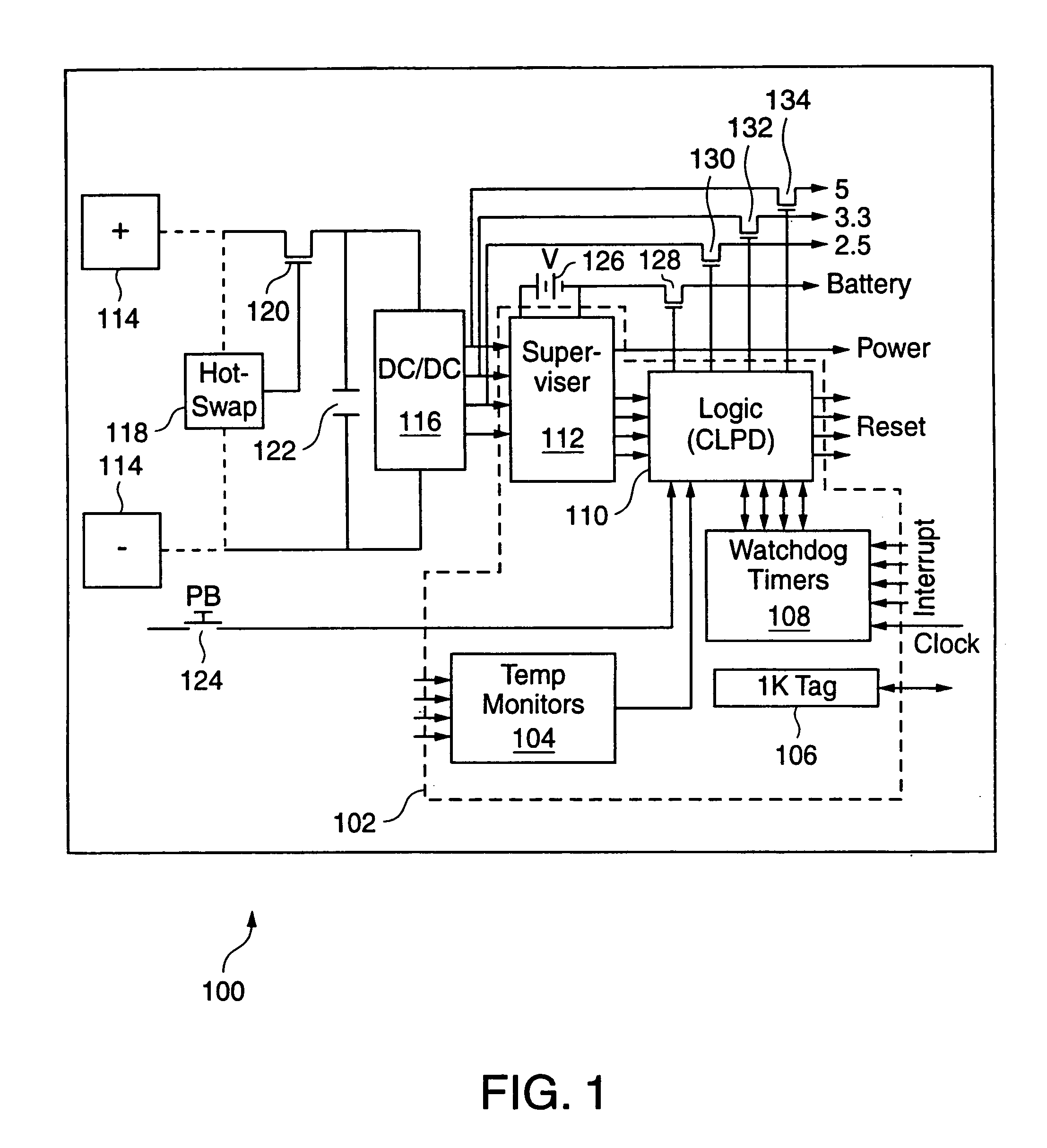
[0029]FIG. 1 illustrates an exemplary block diagram for a system 100 incorporating a programmable power management system 102 in accordance with an embodiment of the present invention. System 100, which illustrates a portion of an electronic device or system, includes a high direct-current (DC) supply voltage 114 having positive and negative terminals that feed a DC-to-DC (DC / DC) converter 116. A capacitor 122 provides signal conditioning and a hot-swap selector 118 controls a transistor 120 that allows the selection of supply voltage 114. DC / DC converter 116 generates a number of DC voltage outputs that are monitored by programmable power management system 102 and that are also supplied to various components of the electronic device (not shown). For example, DC / DC converter 116 may generate DC voltages of 5 V, 3.3 V, 2.5 V, and 1.8 V.

[0030]Programmable power management system 102 includes a supervisor circuit 112, logic circuit 110, watchdog timers 108, a memory (e.g., 1 K tag memo...


PUM


Abstract

A programmable power management integrated circuit includes analog input monitors that receive analog input signals that correspond to voltage, current, or temperature measurements. The analog input monitors apply programmable thresholds to the measurements and output the results to a programmable logic device, which may generate various status and/or control signals to the system being monitored. The programmable logic device controls FET drivers that can switch on and off power to the monitored system. The programmable power management integrated circuit may also comprise an internal oscillator, a serial interface, an in-system programmable interface, a joint test action group interface, a memory that stores identification information, and a register for capturing system information during power-down.

Description

RELATED APPLICATION DATA[0001]This application is a continuation of application Ser. No. 09 / 732,216, filed Dec. 6, 2000, now U.S. Pat. No. 6,735,706.BACKGROUND OF THE INVENTION[0002]1. Field of the Invention[0003]The present invention relates generally to electronic devices and, more particularly, to programmable power management systems and methods.[0004]2. Related Art[0005]A typical electronic device, which includes one or more printed circuit boards that form a complex electronic system, requires multiple voltages for supplying power to numerous components. For example, the components may include a fan requiring 12 volts (V), memory devices requiring 2.5 V and 1.8 V, a microprocessor requiring 2.5 V and 1.8 V, analog circuits requiring 5 V, and logic devices requiring 5 V, 3.3 V, and 2.5 V. These components may further require a complex power-on or reset sequence that employs a timed, defined, reset signal. Additionally, many of these components cannot tolerate significant voltag...

Claims


Application Information

Patent Timeline
IPC IPC(8): G06F1/26G01N27/416G06F1/24G06F1/28
CPCG06F1/28G06F1/24
Inventor TOMLINSON, JOCK F.WILKINSON, DAVID C.BENNETT, JAMES J.MORSE, DOUGLAS C.
Owner LATTICE SEMICON CORP
Why Eureka
Try Eureka