Method of measuring unilateral flow rate of vehicles

a technology of vehicle flow rate and flow rate, which is applied in the direction of mechanical measuring arrangement, force/torque/work measurement apparatus, instruments, etc., can solve the problems of reducing reliability, requiring a lot of time and labor, and unable to obtain true data, so as to shorten the measuring time, prevent damage to the vehicle body and tires, and calculate the lateral displacement amount with accuracy

Inactive Publication Date: 2006-09-05
HONDA MOTOR CO LTD
View PDF26 Cites 6 Cited by
  • Summary
  • Abstract
  • Description
  • Claims
  • Application Information

AI Technical Summary

Benefits of technology

[0010]Therefore, there is no need to conduct an actual traveling test on each vehicle type and the lateral displacement amount can be calculated even if the vehicle does not move laterally or yaw to such a degree as to be detectable. Therefore, it is possible to shorten a measuring time. Moreover, because measuring members need not be brought into contact with a vehicle body or tires, damage to the vehicle body and tires can be prevented, influence of projections and depressions on side faces of a tire can be avoided, and the lateral displacement amount can be calculated with accuracy.

Problems solved by technology

In the former prior art, however, the data showing the correlation between the load cell input load and the lateral displacement amount need be obtained for each vehicle type, which require much time and labor.
Moreover, because the data are obtained by bringing the adjusting wheels into contact with side faces of a tire of the respective wheels, data values are affected by projections and depressions on the side faces, true data cannot be obtained, and reliability decreases.
Furthermore, contact marks may be left on the tires by the adjusting wheels which have come in contact with the tires.
Even if the vehicle is displaced laterally, much time is required for the vehicle to move laterally or yaw to such a degree as to be detected and it is difficult to measure in a short time.
Moreover, because the measuring rollers are brought into contact with the side sills, the side sills may be damaged.

Method used


Image

  • Method of measuring unilateral flow rate of vehicles
  • Method of measuring unilateral flow rate of vehicles
  • Method of measuring unilateral flow rate of vehicles

Examples


Embodiment Construction

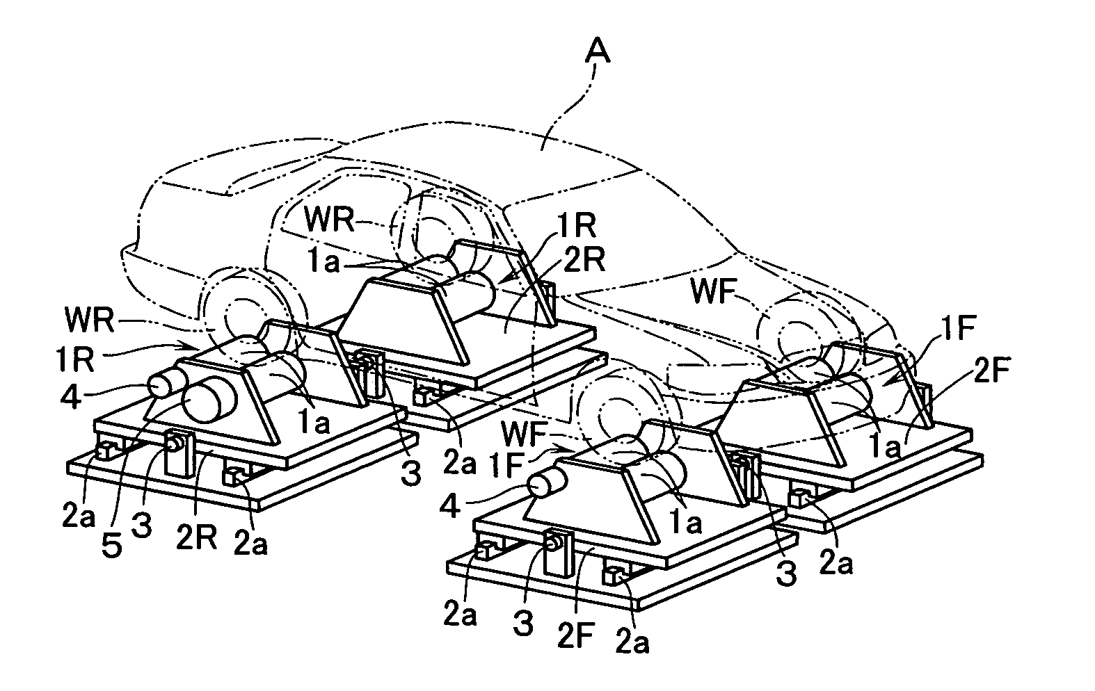
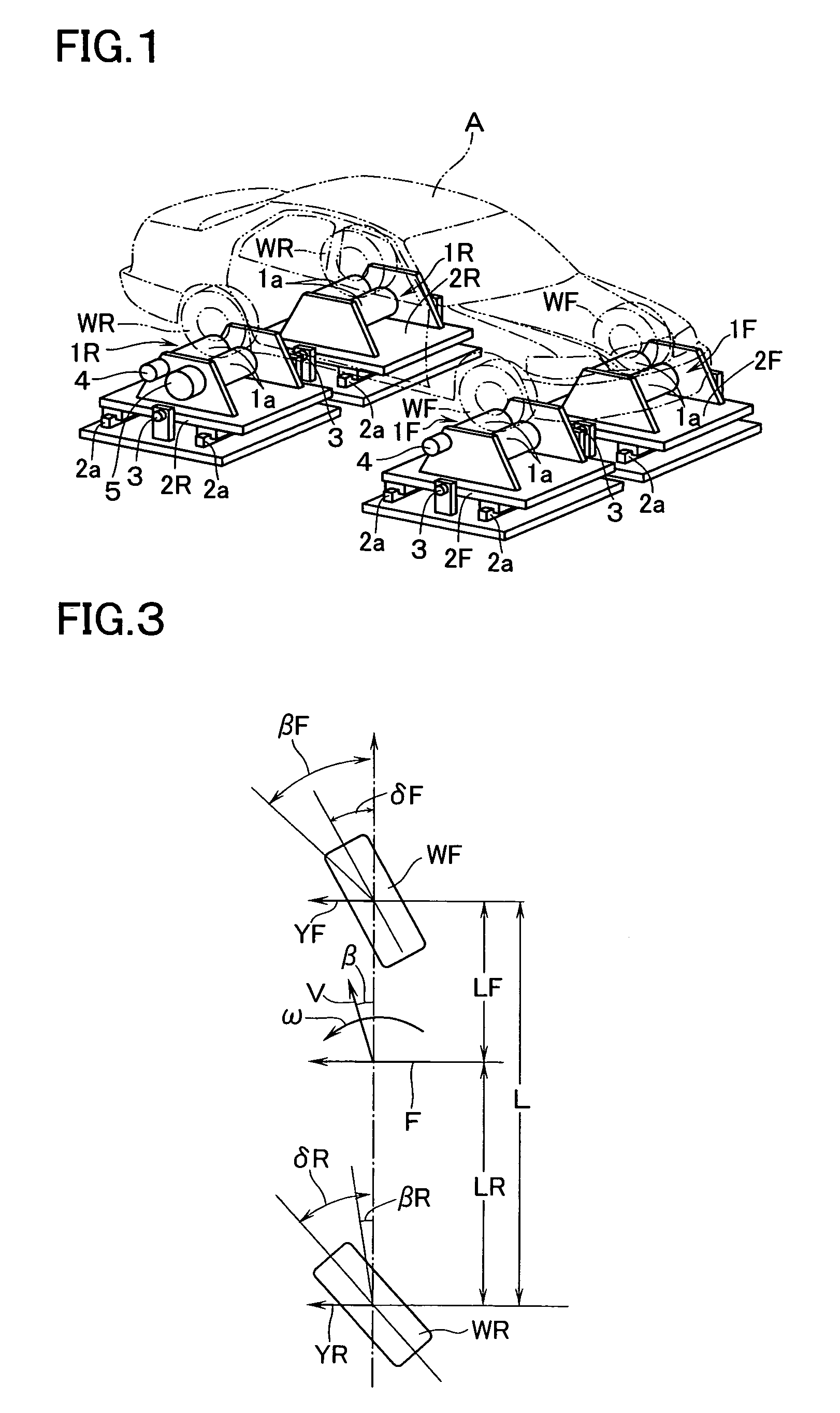
[0014]FIG. 1 shows a bench testing machine including a pair of right and left front wheel rollers 1F, 1F on which right and left front wheels WF of a vehicle A are placed respectively and a pair of right and left rear wheel rollers 1R, 1R on which right and left rear wheels WR of the vehicle A are placed respectively. The respective front wheel and rear wheel rollers 1F and 1R are respectively formed of front and rear two divided rollers 1a, 1a axially supported on respective roller support frames 2F, 2R. The respective roller support frames 2F, 2R are supported to be movable in a lateral direction along guide rails 2a. Detectors 3 such as load cells for detecting lateral forces acting on the respective rollers 1F and 1R through the respective roller support frames 2F and 2R are provided. Furthermore, speed meters 4 for detecting rotational speeds of the respective rollers 1F, 1R, a motor 5 for driving the roller 1R for the rear wheels WR which are follower wheels, and a computer (n...


PUM

PropertyMeasurementUnit
rotational speedsaaaaaaaaaa
distanceaaaaaaaaaa
speedaaaaaaaaaa

Abstract

The invention makes it possible to measure a lateral displacement amount of a vehicle accurately in a short time on a bench testing machine without damaging a vehicle body and tires.Respective rollers 1F, 1R on which respective wheels WF, WR of the vehicle A are placed respectively are made movable in a lateral direction. In a state in which the respective wheels WF, WR are rotating at a predetermined speed, lateral forces (cornering forces) acting on the respective rollers 1F, 1R are detected by respective detectors 3. Then, a yaw angle speed when the vehicle A is brought into a state of steady circular turning is calculated based on the lateral forces acting on the respective rollers 1F, 1R and the lateral displacement amount is calculated from the yaw angle speed.

Description

CROSS-REFERENCE TO RELATED APPLICATION[0001]This application is a National Stage entry of International Application No. PCT1JP02102485, the entire specification claims and drawings of which are incorporated herewith by reference.TECHNICAL FIELD[0002]The present invention relates to a method of measuring a lateral displacement amount of a vehicle (a value indicating a distance by which the vehicle is displaced rightward or leftward while traveling a reference distance) generated due to dispersions in assembly accuracy of a vehicle body, accuracy of wheel alignment, and the like when the vehicle travels with its steering wheel in a straight-ahead state.BACKGROUND ART[0003]Conventionally, there is a known method as disclosed in Japanese Patent Application Laid-open No. 6-331505 in which a bench testing machine having rollers for front wheels and rollers for rear wheels is used and the front and rear wheels of a vehicle are rotated on the corresponding rollers to measure a lateral displ...

Claims


Application Information

Patent Timeline
Patent Type & Authority Patents(United States)
IPC IPC(8): G01B5/24G01L3/26G01L5/20G01M17/007
CPCG01M17/0072G01L5/20
Inventor HARA, KIYONOBUNOGUCHI, SUMIOKURAI, KENICHIRO
Owner HONDA MOTOR CO LTD
Why Eureka
Try Eureka