Pneumatically operated projectile launching device

a projectile and pneumatic technology, applied in the field of pneumatically operated projectile launchers, can solve the problems of paintball breakage, adversely affecting the accuracy with which the projectile can be fired to strike the intended target, etc., and achieve the effect of minimizing recoil, increasing recoil, and improving accuracy

Inactive Publication Date: 2006-09-05
KEE ACTION SPORTS I
View PDF55 Cites 18 Cited by
  • Summary
  • Abstract
  • Description
  • Claims
  • Application Information

AI Technical Summary

Benefits of technology

[0008]Finally, the present invention also provides a significant accuracy advantage over all prior art spring-loaded guns at all pneumatic operating pressures, due to the minimized recoil experienced after a shot is fired. Typical spring-loaded guns exhibit greater recoil than does the invention, due to the non-linear reaction forces created on the gun body by the expansion of the spring. In contrast, the elimination of spring loading in the present invention eliminates these non-linear forces, minimizing the amount of recoil experienced and thus allowing greater accuracy over all types of existing spring-loaded gun designs in the firing of a shot.

Problems solved by technology

In the case of any flexible projectile in general and particularly in the case of paintballs, this non-linear transformation of energy causes some deformation in the shape of the projectile that alters the ballistic forces created upon it in flight, adversely affecting the accuracy with which the projectile can be fired to strike its intended target.
This increased thickness has in turn created a problem with paintball breakage as it impacts its target.

Method used


Image

  • Pneumatically operated projectile launching device
  • Pneumatically operated projectile launching device
  • Pneumatically operated projectile launching device

Examples


Embodiment Construction

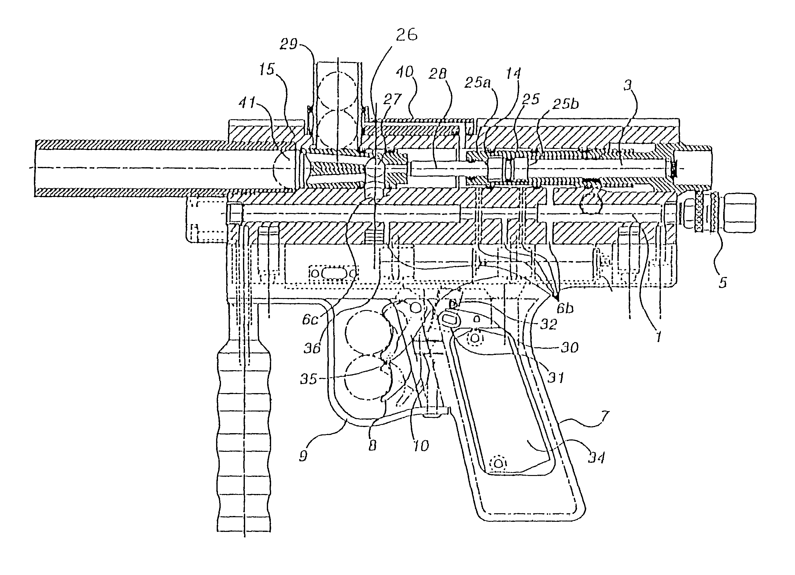
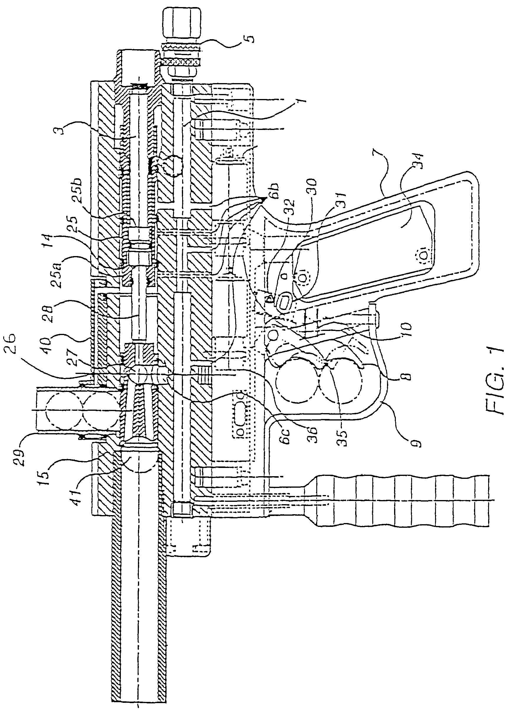
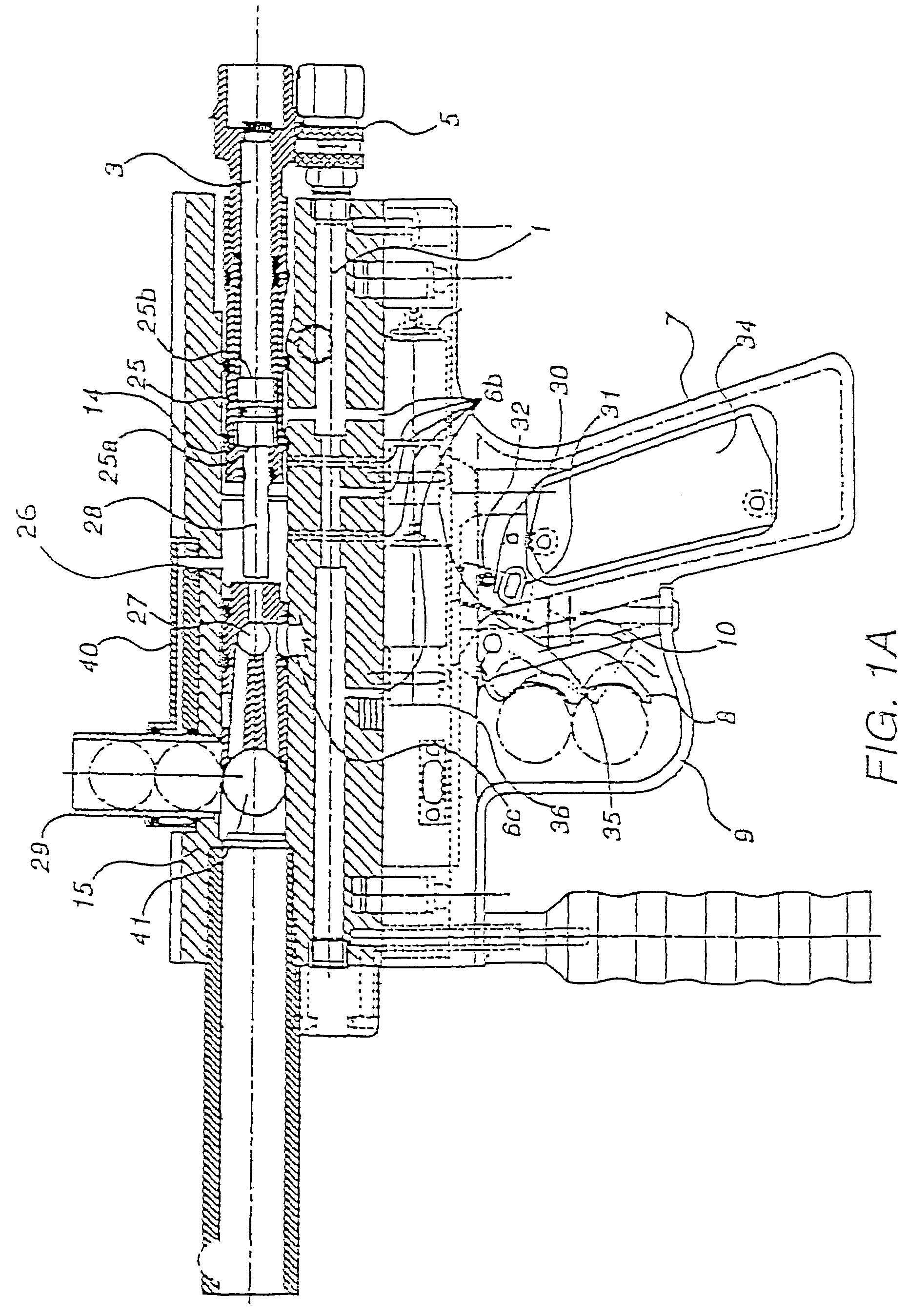
[0026]The pneumatically operated projectile launching device is preferably comprised of three principal elements: a body which houses and interconnects all of the pneumatic components and also houses the electrical power source; a grip mounted to the body which includes a trigger and an electrical switch that activates the launching sequence; and an electrical control unit housed within both the body and the grip which directs flow between the pneumatic components to load, cock and fire the gun

[0027]As shown in FIG. (2), the body preferably has three cylindrical pneumatic bores with axes that are preferably parallel to the longitudinal axis of the gun body 40. The gun body 40 can be made of materials suitable in the art for withstanding the force of the launching sequence such as metal or plastic. The first bore 1 contains compressed gas and is preferably sealed by a removable fitting 5 which is removed to inject the gas. The first bore 1 is preferably in communication with the seco...


PUM


Abstract

A pneumatically operated projectile launching device preferably comprises an electro-pneumatic flow distribution mechanism that receives and directs compressed gas to a pneumatic mechanism to open a bolt.

Description

[0001]This application is a continuation of, and claims priority from, U.S. patent application Ser. No. 10 / 254,891, filed on Sep. 24, 2002 now U.S. Pat. No. 6,637,421; which is a continuation of, and claims priority from, U.S. patent application Ser. No. 09 / 490,735 (now U.S. Pat. No. 6,474,326 B1), filed Jan. 25, 2000; which is a continuation of, and claims priority from, U.S. patent application Ser. No. 08 / 586,960 (now U.S. Pat. No. 6,035,843), filed Jan. 16, 1996, the contents of which are herein incorporated by reference in their entirety.FIELD OF THE INVENTION[0002]The present invention relates to a pneumatically operated projectile launching device. A preferred embodiment of the invention is designed for use in the recreational sport of “Paintball” (also known as “Survival” or “Capture the Flag”).BACKGROUND OF THE INVENTION[0003]The current invention consists of a device for launching a projectile using pneumatic force. Guns using pneumatic force to propel a projectile are well...

Claims


Application Information

Patent Timeline
Patent Type & Authority Patents(United States)
IPC IPC(8): F41B11/00F41B11/26A63F9/02F41B11/02F41B11/32F41B11/62
CPCF41B11/52F41B11/57F41B11/71F41B11/721F41B11/62
Inventor SMITH, DAVID L.GASTON, RAYMOND S.GARDNER, JR., WILLIAM M.GARDNER, ADAM C.
Owner KEE ACTION SPORTS I
Why Eureka
Try Eureka