Ventilated seat

a ventilated seat and seat technology, applied in the field of ventilated seats for vehicles, can solve the problems of insufficient resolution of problems, difficult to warm or cool the seats quickly, and excessive sweating of occupants, and achieve the effects of maximizing comfort, efficient evaporation, and maximizing comfor

Inactive Publication Date: 2006-09-05
GENTHERM GMBH
View PDF2 Cites 125 Cited by
  • Summary
  • Abstract
  • Description
  • Claims
  • Application Information

AI Technical Summary

Benefits of technology

[0007]A fan (vacuum or forced air) is connected to an extension or tongue provided on a bag that is formed by the first inner layer and the lower surface layer and air moves through the second inner layer into or out of the ventilation holes provided in the first inner layer and hence through the upper surface layer. A vacuum would draw interior air from the vehicle through the occupant's clothes, through the ventilated seat pad assembly and out through the vacuum device, or the reverse would occur if it were desired to use forced air to heat or cool the air leaving the pad. The pad assembly of the present invention allows the occupant's perspiration to evaporate efficiently from his skin and clothing or to warm or cool the occupant more quickly than has previously been possible. Preferably, the occupant can adjust the airflow rate through the pad to maximize comfort at any time.

Problems solved by technology

When driving a car in hot weather, occupants may experience excessive sweating from contact with the vehicle seat, because the seat prevents or blocks the body's ability to radiate excess heat.
A disadvantage of both solutions is that areas of the occupant's body are in contact with the vehicle seat preventing any cooling airflow from reaching those areas.
In cold weather, the reverse phenomena may occur, i.e., cold seats may be difficult to warm quickly due to occupant contact with the seat.
A disadvantage of these seat covers is that they rely only on passive air flow and thus they do not fully resolve the issues discussed above.

Method used


Image

  • Ventilated seat
  • Ventilated seat
  • Ventilated seat

Examples


Embodiment Construction

[0016]The following description of the preferred embodiment is merely exemplary in nature and is in no way intended to limit the invention or its application or uses.

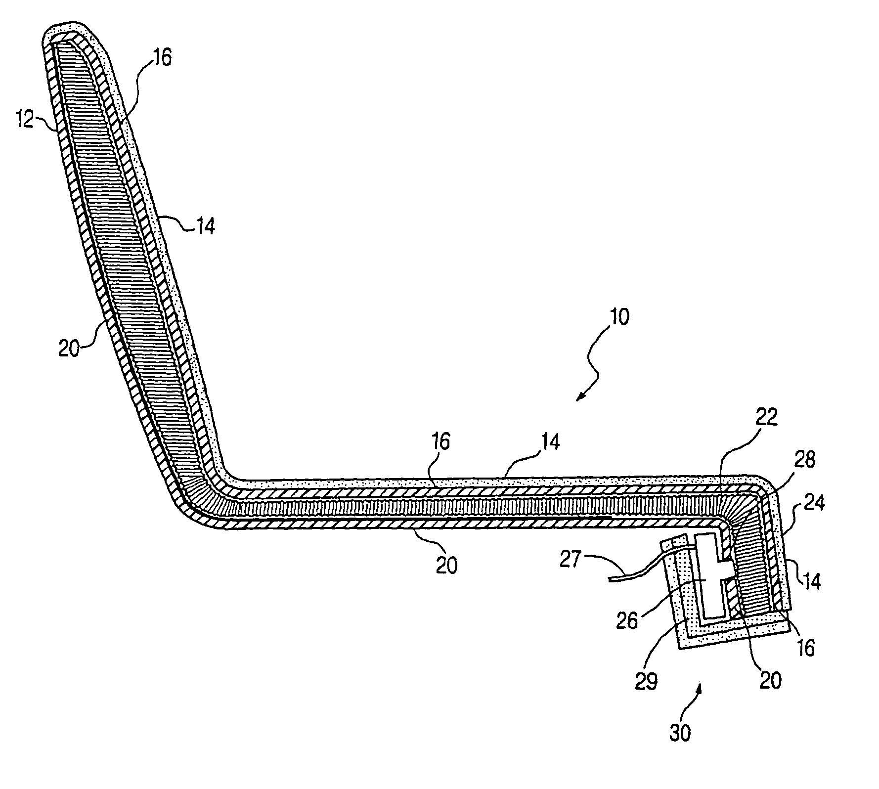
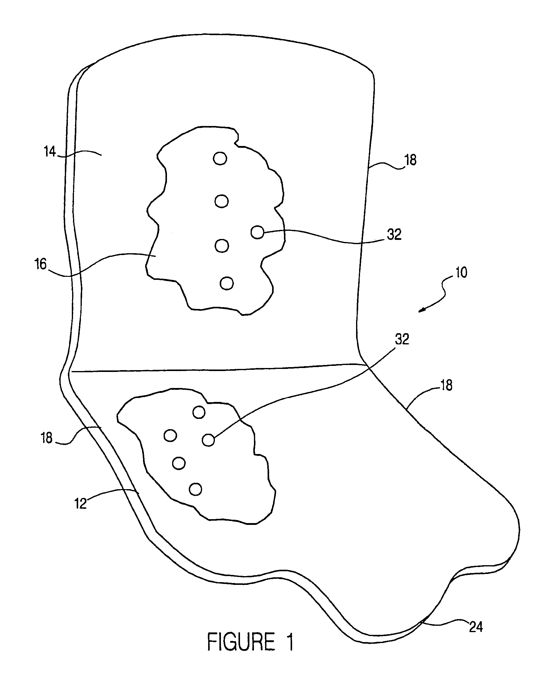
[0017]As shown in FIG. 1, the portable ventilated seat pad assembly 10 of the preferred embodiment of the invention includes a pad 12 which lays on top of a vehicle seat 44, 45 (FIG. 4).

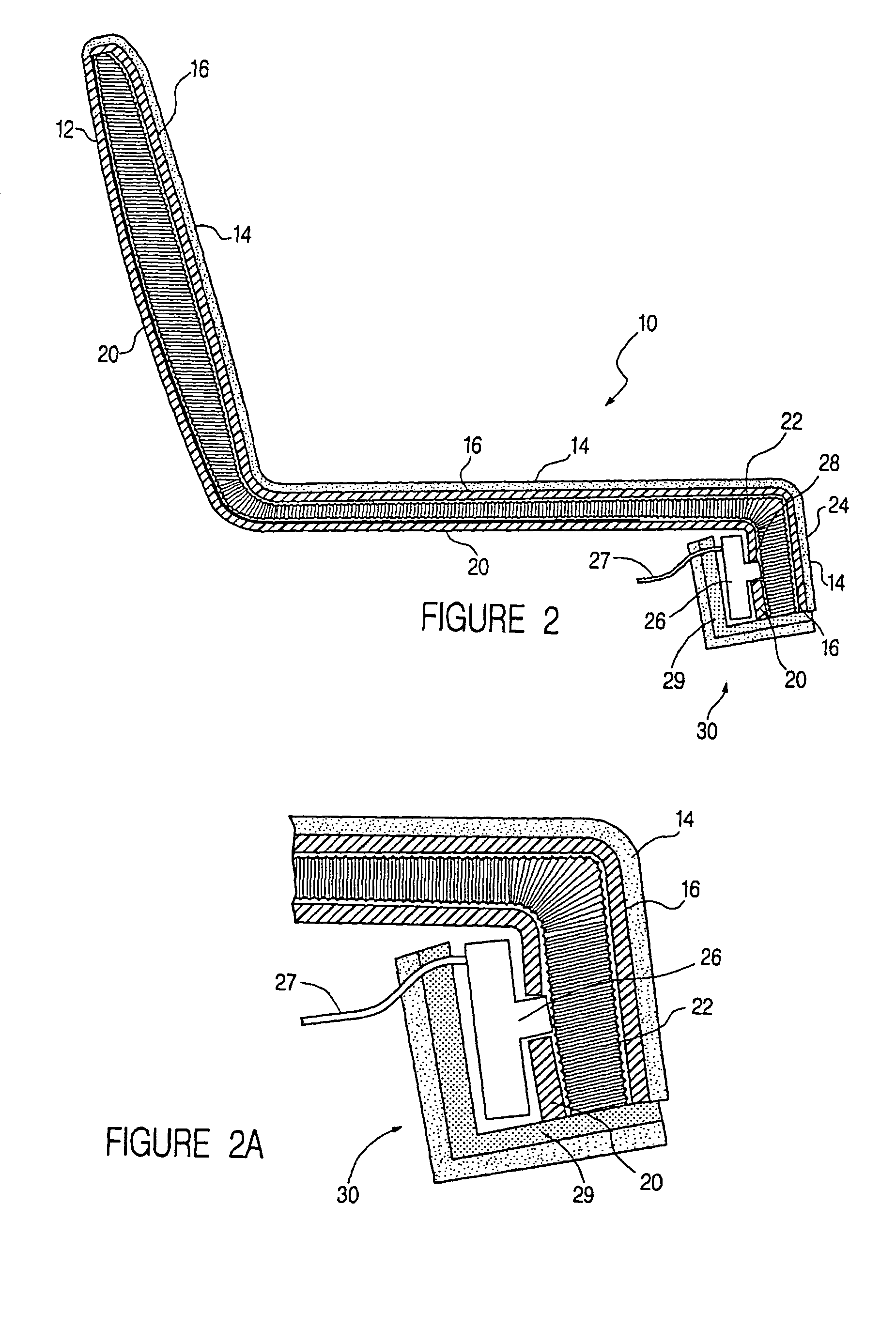
[0018]As best shown in FIGS. 2 and 3, the pad 12 includes an upper surface layer 14. The upper surface area 14 is preferably formed of a porous material, e.g., fabric or perforated leather. A first inner layer 16 is formed of a non-porous material, as is a lower surface layer 20. Upper surface layer 14, first inner layer 16, and lower surface layer 20 are attached, for example, by sewing 18 (FIG. 1), forming an air impermeable bag between the first inner layer 16 and the lower surface layer 20.

[0019]An expanded, porous second inner layer 22 is located between non-porous layers 16, 20 and is preferably 5900 series spacer fabric available ...


PUM


Abstract

A ventilated vehicle seat includes a porous upper surface layer, a resinous film non-porous first layer, a non-porous second layer, and a spacer layer. The resinous film non-porous first layer is beneath the upper surface layer and includes ventilation holes. The spacer layer is between the non-porous layers for providing cushioning and for ensuring airflow in lateral, longitudinal and perpendicular directions, even when the seat is occupied. The spacer layer is fixed in position between the first layer and the second layer for preventing slipping of the spacer layer.

Description

CROSS REFERENCE TO RELATED APPLICATIONS[0001]The present application is a continuation of U.S. application Ser. No. 10 / 445,506, filed by Ekern et al. on May 27, 2003, now U.S. Pat. No. 6,840,576, entitled “Ventilated Seat,” which is a continuation of U.S. application Ser. No. 09 / 755,506, filed by Ekern et al. on Jan. 5, 2001, now U.S. Pat. No. 6,629,724, entitled “Ventilated Seat,” both of which are incorporated herein by reference.FIELD OF THE INVENTION[0002]This invention generally relates to a ventilated seat for a vehicle. More specifically, this invention relates to a portable ventilated seat for a vehicle including a top pad assembly that forms at least a seat cushion, and preferably a seat cushion and seat back, suitable for use with any vehicle seat. Air passes through the seating surface of the pad assembly by suction or forced air flow.BACKGROUND OF THE INVENTION[0003]When driving a car in hot weather, occupants may experience excessive sweating from contact with the vehic...

Claims


Application Information

Patent Timeline
Patent Type & Authority Patents(United States)
IPC IPC(8): A47C7/74A47C27/15A47C27/00B60N2/56
CPCB60N2/5635B60N2/565
Inventor EKERN, DAVID F.BEDRO, RONALD G.
Owner GENTHERM GMBH
Why Eureka
Try Eureka