
Takeout and transfer apparatus and method for a wheel blow molding machine

Inactive Publication Date: 2006-09-05
GRAHAM PACKAGING CO LP
View PDF28 Cites 7 Cited by
  • Summary
  • Abstract
  • Description
  • Claims
  • Application Information

AI Technical Summary

Benefits of technology

[0011]Another object of the present invention is to provide a high-speed bottle transfer system capable of transferring at least about 500 to about 850 bottles per minute from a vertically-disposed wheel blow molding machine to a horizontally-disposed conveyor.
[0012]A further object of the present invention is to provide a high-speed bottle transfer system which requires no significant preventative maintenance and which experiences minimal, if any, downtime.

Problems solved by technology

The increased rate of forming bottles in a wheel blow molding machine and the use of multiple parisons for forming multiple blown articles in each mold significantly complicates the task of removing blown articles from a wheel blow molding machine and placing the blown articles in a uniform position on a horizontally disposed takeaway conveyor.
In addition, vacuum and / or mechanical pick and place machines have relatively complicated structures and are relatively expensive to build and / or purchase.
They require frequent maintenance and are prone to experiencing mechanical and pneumatic failures.
The downtime of the pick and place machines can significantly reduce the overall rate of manufacture of containers.

Method used


Image

  • Takeout and transfer apparatus and method for a wheel blow molding machine
  • Takeout and transfer apparatus and method for a wheel blow molding machine
  • Takeout and transfer apparatus and method for a wheel blow molding machine

Examples


Embodiment Construction

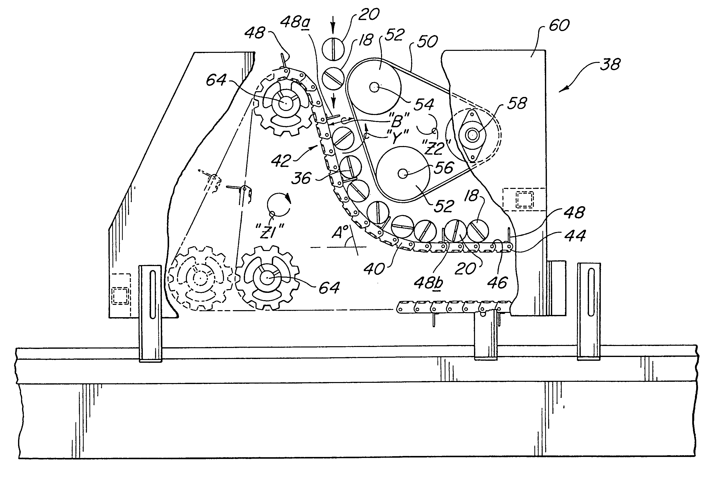
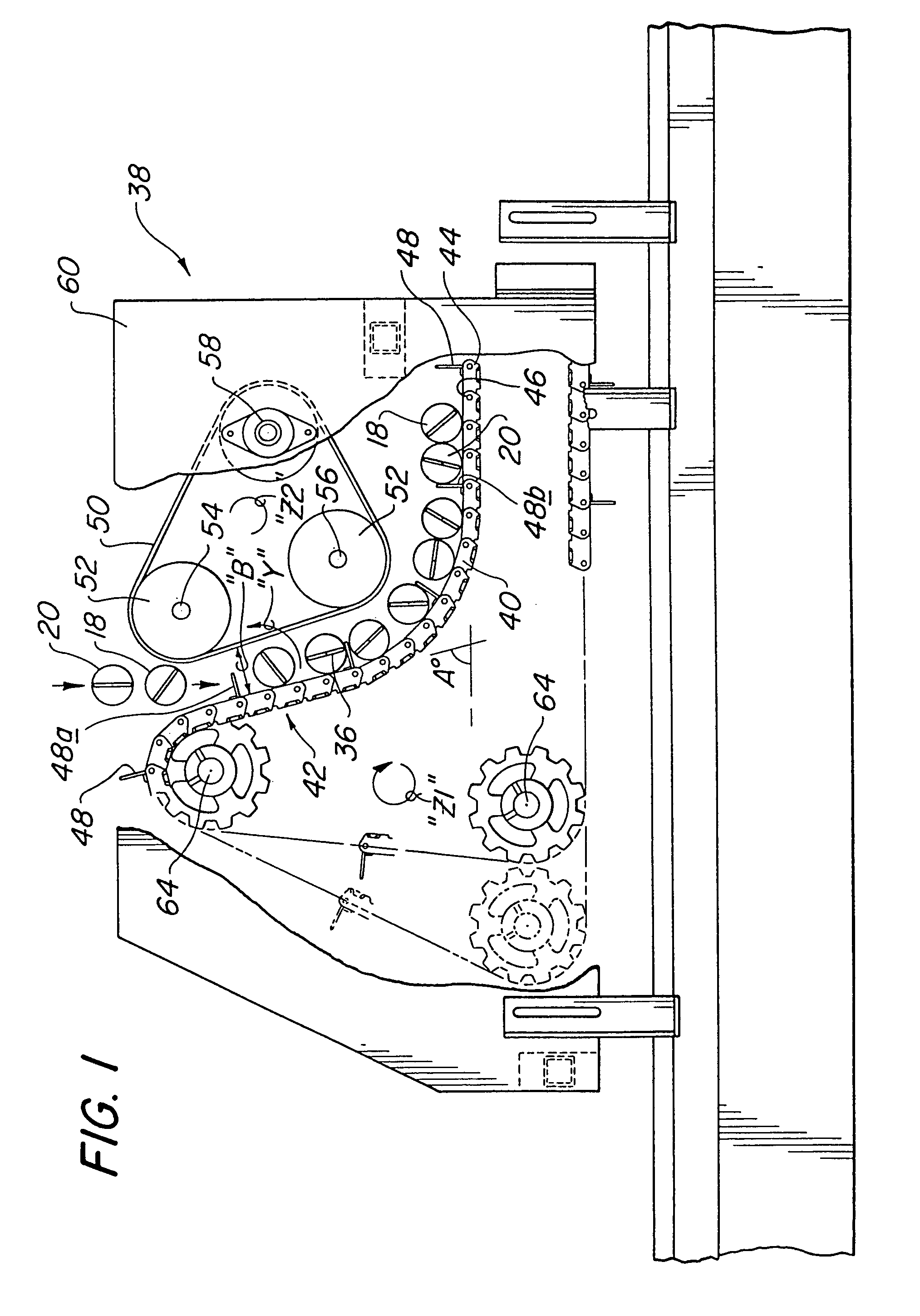
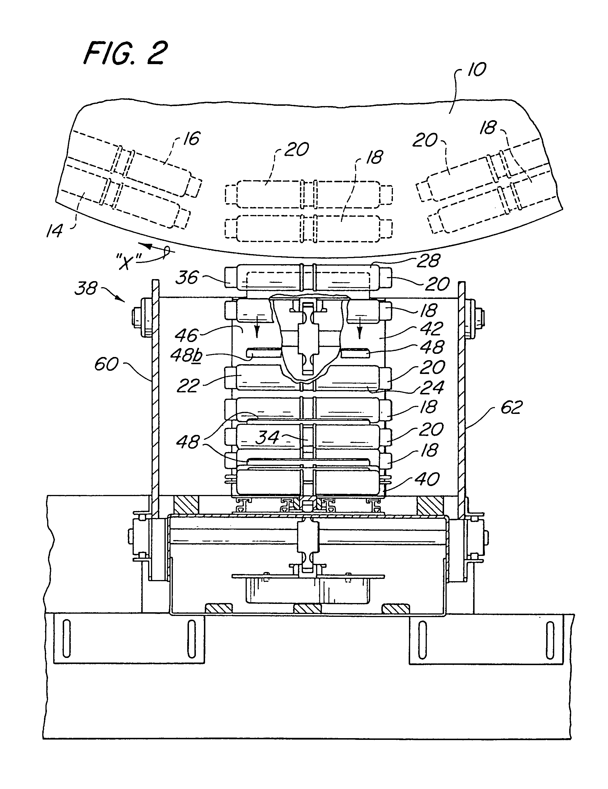
[0021]As referenced above, a vertically-disposed wheel blow molding machine includes an outer peripheral circular array of blow molds which follow a circular path of travel as the wheel blow molding machine continuously revolves at a constant speed. For purposes of example, a portion of a wheel blow molding machine 10 rotating in a clock-wise direction “X” is illustrated in FIG. 2, and a blow mold 12 is illustrated in FIG. 4. Each mold 12 is capable of opening to receive at least one molten tube of thermoplastic material, ie. a parison, and closing to confine the parison within a cavity formed by the inner walls of the mold. As the mold rotates, a blow pin is inserted into the parison to expand it into the cavity of the closed mold, and before one complete revolution, the mold opens to release the blown article. Thus, at the end of a full revolution, the mold is empty and open in a condition ready to receive another parison.

[0022]The takeout and transfer apparatus of the present inv...


PUM

PropertyMeasurementUnit
Angleaaaaaaaaaa
Angleaaaaaaaaaa
Timeaaaaaaaaaa

Abstract

Apparatus and method for transferring hollow blow molded articles from a vertically disposed wheel blow molding machine to a horizontally-disposed takeaway conveyor. Each mold on the wheel releases multiple blown articles at the six o'clock position on the wheel such that the articles fall freely from the wheel. An inclined end of a takeaway conveyor is located directly underneath the six o'clock position in order to receive the free falling blown articles and transport them to a horizontal transporting section of the takeaway conveyor. Flanges which extend upwardly from the conveying surface of the takeaway conveyor in combination with a powered endless positioning belt which extends a spaced distance along the inclined receiving end are utilized to confine the blown articles on the receiving end and uniformly position the blown articles on the takeaway conveyor.

Description

CROSS REFERENCE TO RELATED APPLICATION[0001]The present application is a divisional of application Ser. No. 09 / 877,892 filed on Jun. 8, 2001 now U.S. Pat. No. 6,669,461.FIELD OF THE INVENTION[0002]The present invention relates to a transfer mechanism and method for efficiently transferring blow-molded articles from a vertically-disposed wheel blow molding machine to a horizontally-disposed takeaway conveyor, and more particularly, the present invention relates to a method and apparatus in which blown articles are released in free fall from a wheel blow molding machine and are positioned in an orderly uniform manner on a takeaway conveyor for transport to further operations, such as trimming.BACKGROUND OF THE INVENTION[0003]One type of blow molding machine utilized to manufacture blow molded containers is a wheel blow molding machine which is vertically disposed and rotates about a horizontal axis. An example is illustrated in FIG. 1 of U.S. Pat. No. 5,681,597 issued to Aguilar et al...

Claims


Application Information

Patent Timeline
IPC IPC(8): B29C49/70B29C49/04B29C49/36B29C49/42B65G47/84
CPCB29C49/421B65G47/841B29C49/04B29C49/36B65G2201/0244B29C2049/4869B29C2793/009B29C2049/048B29C49/04108B29C49/48185B29C49/42069
Inventor TAYLOR, GREGORY D.CRIDER, MATTHEW A.KLINGENMAIER, BERNDENFIELD, JEFFERY C.
Owner GRAHAM PACKAGING CO LP
Learn More