Diffractive security element having an integrated optical waveguide

a technology of optical waveguides and diffractive elements, applied in the direction of printing, other printing materials, instruments, etc., can solve the problems of difficult visual recognition, difficult to recognise the shape of surface elements, and high surface brightness, and achieve the effect of easy visual recognition and simple recognition

Inactive Publication Date: 2006-09-05
OVD KINEGRAM AG
View PDF12 Cites 26 Cited by
  • Summary
  • Abstract
  • Description
  • Claims
  • Application Information

AI Technical Summary

Benefits of technology

[0009]The object of the present invention is to provide an inexpensive diffractive secur...

Problems solved by technology

The disadvantage of the known diffractive security elements lies in the difficulty of visually recognising complicated, optically varying patterns in a narrow solid angle and the extremely high level of surface brightness, at which a surface element occupied by a diffraction grating is visibl...

Method used


Image

  • Diffractive security element having an integrated optical waveguide
  • Diffractive security element having an integrated optical waveguide
  • Diffractive security element having an integrated optical waveguide

Examples


example 1

Change of Color Upon Rotation

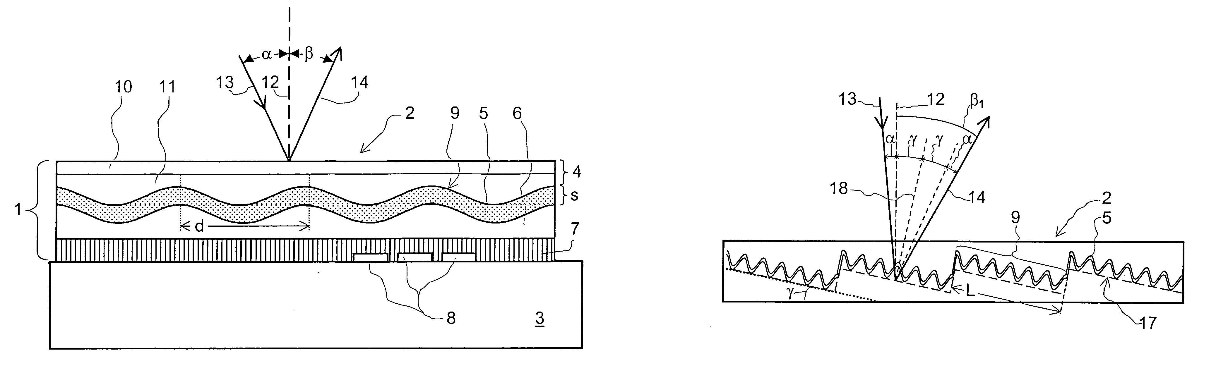
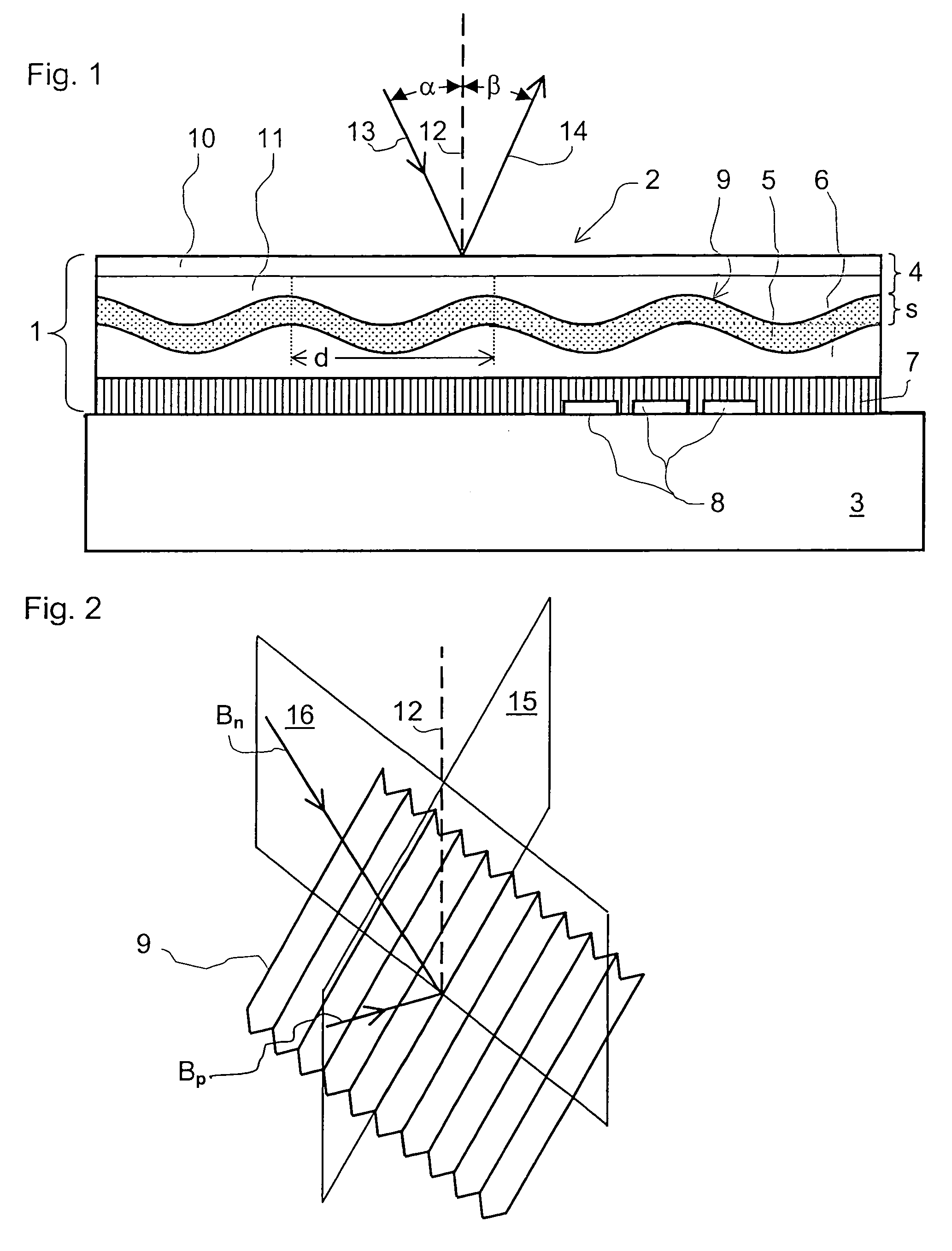
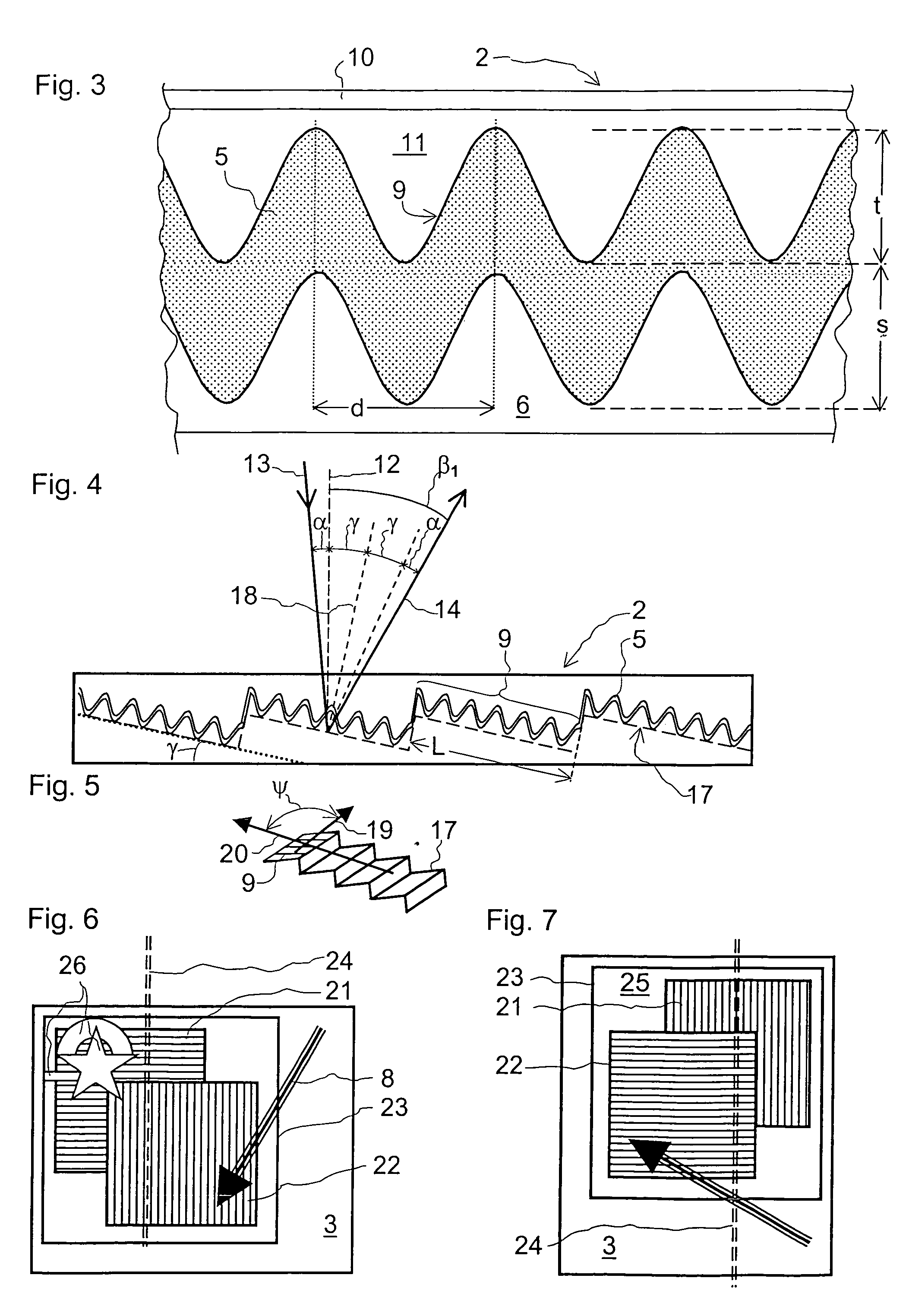
[0033]FIG. 3 shows the waveguide 5 in cross-section on an enlarged scale. The plastic layers, the stabilisation layer 10, the shaping layer 11, the protective layer 6 and the adhesive layer 7 (FIG. 1), in accordance with Table 6 of U.S. Pat. No. 4,856,857, have refractive indices n1 in the range of between 1.5 and 1.6. The dielectric which is transparent for visible light 13 (FIG. 1), with the refractive index n2, is deposited uniformly in a layer thickness d on the optically effective structure 9 formed in the shaping layer 11, so that on the interface towards the protective layer 6 the surface of the waveguide 5 also has the optically effective structure 9. The dielectric is an inorganic compound as mentioned for example in U.S. Pat. No. 4,856,857, Table 1 and in WO 99 / 47983, and is of a value in respect of the refractive index n2 of at least n2=2.

[0034]In an embodiment of the security element 2 the values for the profile depth t of the optically eff...

example 2

Tilting-invariant Color

[0037]Another embodiment of the security element 2 exhibits an advantageous optical behaviour as, upon illumination with white unpolarised light 13, for small tilting angles, corresponding to the angle of incidence between α=10° and α=40°, the color of the diffracted light 14 remains practically invariant. The parameters of the waveguide 5, the layer thickness s and the profile depth t are here linked by the relationship s≈2t. For example the layer thickness s=115 nm and the profile depth t=65 nm. The period length d of the optically effective structure 9 is d=345 nm. In the specified range of the tilt angle with illumination with white unpolarised light 13 in parallel relationship with the grating lines of the optically effective structure 9 the diffracted light 14 is of a red color, to which the light beams BpTM primarily contribute. Upon a rotary movement of the security element 2 through a few degrees of azimuth angle the reflected color remains red while ...

example 3

Color Change Upon Tilting

[0038]If the security element 2 is rotated in such a way that the incident light 13 is directed in perpendicular relationship to the grating lines, the security element 2 of Example 2, upon tilting about an axis in parallel relationship with the grating lines of the diffraction grating, exhibits a color shift: for example the observer views the surface of the security element 2 with perpendicular incidence of light, that is to say with an angle of incidence α=0°, as an orange, with an angle of incidence α=10° the observer sees a mixed color comprising about 67% green and 33% red and with an angle of incidence α=30° he sees an almost spectrally pure blue.


PUM


Abstract

A diffractive security element (2) is divided into surface portions, having an optically effective structure (9) at interfaces embedded between two layers of a layer composite (1) of plastic material. At least the base layer (4), which is to be illuminated, of the layer composite (1) is transparent. The optically effective structure (9) as a base structure has a zero order diffraction grating with a period length of at most 500 nm. In at least one of the surface portions an integrated optical waveguide (5) with a layer thickness (s) of a transparent dielectric is embedded between the base layer (4) and an adhesive layer (7) of the layer composite (1) and/or a protective layer (6) of the layer composite (1), wherein the profile depth of the optically effective structure (9) is in a predetermined relationship with the layer thickness (s). Upon illumination with white incident light (13) the security element (2) produces light (14) which is diffracted in the zero diffraction order, of high intensity and with an intensive color.

Description

[0001]This application claims priority based on PCT Application No. PCT / EP02 / 12243, filed on Nov. 2, 2002 and Swiss Patent Application No. 0084 / 02, filed on Jan. 18, 2002, both of which are incorporated herein by reference in their entirety.BACKGROUND OF THE INVENTION[0002]The invention relates to a diffractive security element which is divided into surface portions with an optically effective structure of interfaces embedded between two layers of a composite of plastic material.[0003]Diffractive security elements of that kind are used for the verification of articles such as banknotes, passes and identity cards of all kinds, valuable documents and so forth in order to be able to establish the authenticity of the article without involving a high level of cost. When the article is issued the diffractive security element is fixedly joined thereto, in the form of a stamp portion cut from a thin layer composite.[0004]Diffractive security elements of the kind set forth in the opening par...

Claims


Application Information

Patent Timeline
IPC IPC(8): G02B5/18B42D15/00B42D25/29
CPCB42D25/29B42D25/328B42D15/0033B42D15/0053B42D15/0073
Inventor SCHILLING, ANDREASTOMPKIN, WAYNE ROBERTSTAUB, RENE
Owner OVD KINEGRAM AG
Why Eureka
Try Eureka