
Methods and apparatus for determining component alignment

a multi-modality system and alignment status technology, applied in the field of imaging systems, can solve problems such as inability to properly register and misregister images

Active Publication Date: 2006-09-05
GE MEDICAL SYST GLOBAL TECH CO LLC
View PDF21 Cites 23 Cited by
  • Summary
  • Abstract
  • Description
  • Claims
  • Application Information

AI Technical Summary

Problems solved by technology

This should be readily apparent, since a misalignment of the coordinate systems will directly result in a misregistration of the images.
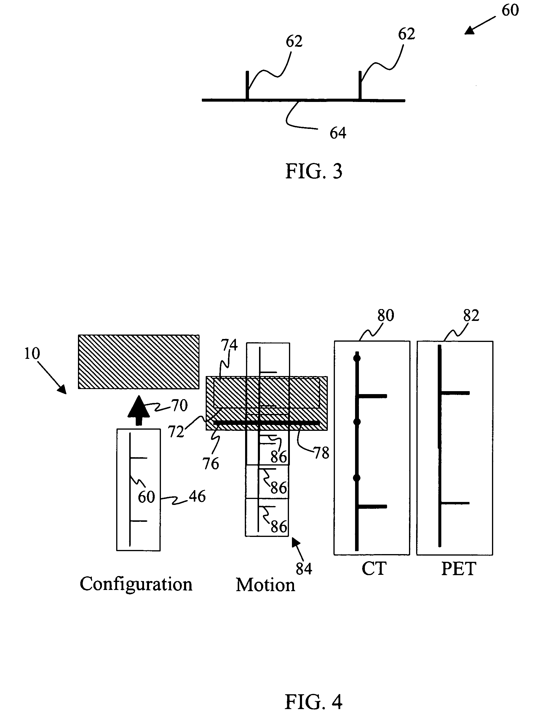
Even if the CT and PET are perfectly aligned, a misaligned table will produce different artifacts in the CT and PET volumes, which cannot be properly registered.

Method used


Image

  • Methods and apparatus for determining component alignment
  • Methods and apparatus for determining component alignment
  • Methods and apparatus for determining component alignment

Examples


Embodiment Construction

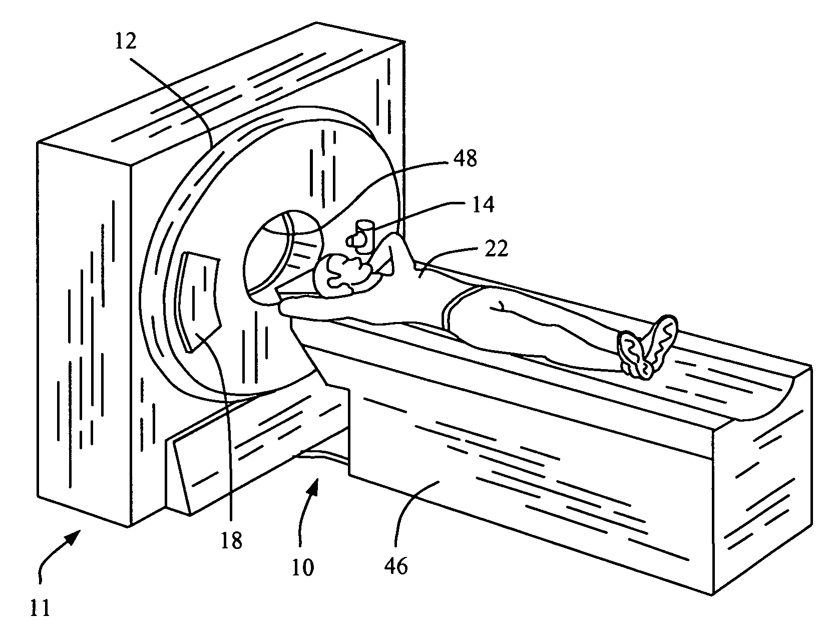
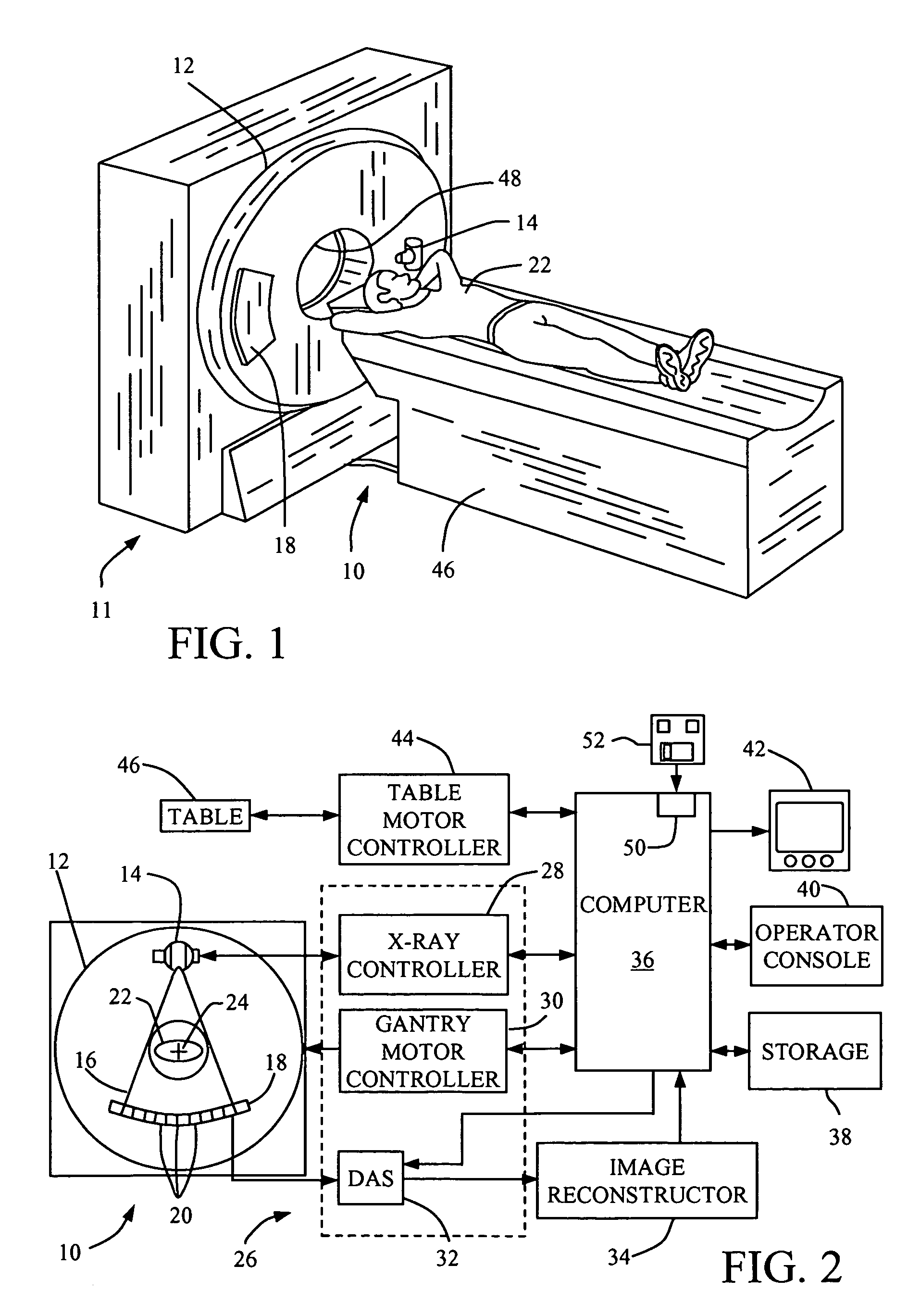
[0021]In some known CT imaging system configurations, an x-ray source projects a fan-shaped beam which is collimated to lie within an X–Y plane of a Cartesian coordinate system and generally referred to as an “imaging plane”. The x-ray beam passes through an object being imaged, such as a patient. The beam, after being attenuated by the object, impinges upon an array of radiation detectors. The intensity of the attenuated radiation beam received at the detector array is dependent upon the attenuation of an x-ray beam by the object. Each detector element of the array produces a separate electrical signal that is a measurement of the beam intensity at the detector location. The intensity measurements from all the detectors are acquired separately to produce a transmission profile.

[0022]In third generation CT systems, the x-ray source and the detector array are rotated with a gantry within the imaging plane and around the object to be imaged such that the angle at which the x-ray beam ...


PUM


Abstract

A method for determining component misalignment in a multi-modality imaging system including a first modality unit, a second modality unit, and a table, includes imaging an object with the first modality unit to generate a first image, imaging the object with the second modality unit to generate a second image, and determining a table alignment status using the first and second images.

Description

BACKGROUND OF THE INVENTION[0001]This invention relates generally to imaging systems capable of scanning objects in multi modalities and more particularly to a method for determining an alignment status of the multi-modality system.[0002]The present invention is directed toward multi-modal imaging systems capable of scanning using different modalities, such as, for example, but not limited to, Positron Emission Tomography (PET) and Computed Tomography (CT). The difference between multi-mode and multi-modality is that in multi-mode systems the same hardware is utilized to perform scans in different modes (e.g., a radiation source and a radiation detector is used in both a flouro mode and a tomosynthesis mode), while in a multi-modal system (multi-modality system), although some of the same hardware is utilized to perform different scans (e.g., an image produced by PET is processed and displayed respectively, by the same computer and display, as an image produced by CT), the data acqu...

Claims


Application Information

Patent Timeline
IPC IPC(8): G06K9/00A61B6/04G06K9/36G06T7/00
CPCG06T7/0024A61B6/037G06T2207/10081G06T2207/10104A61B6/584G06T2207/30204G06T2207/30004G06T7/30
Inventor STEARNS, CHARLES WILLIAM
Owner GE MEDICAL SYST GLOBAL TECH CO LLC
Learn More