
Method and apparatus determining the presence of interference in a wireless communication channel

a wireless communication channel and interference detection technology, applied in the direction of electrical equipment, transmission, transmission monitoring, etc., can solve the problems of low channel quality, large noise relative to signal levels, data reception errors, etc., and achieve the effect of shortening the overall observation process

Active Publication Date: 2006-09-05
QUALCOMM INC
View PDF18 Cites 125 Cited by
  • Summary
  • Abstract
  • Description
  • Claims
  • Application Information

AI Technical Summary

Benefits of technology

[0014]In one embodiment of the present inventive RF interference detection method and apparatus, an observation accelerator is used to accelerate the noise and interference data sampling process. The observation accelerator produces an estimate of whether or not a channel has an interferer present and counts the number of times this occurs. Observation of the channel stops when either of two events occurs. If the number of interference hits reaches a predetermined threshold level, or if the total number of observations reaches a predetermined threshold level, the observation of the channel stops. The observation accelerator thereby shortens the overall observation process by ensuring that a channel is observed for a duration that is sufficient to obtain a reasonable estimate of interference levels. In practice, only a few interference samples are required.

Problems solved by technology

As is well known, data reception errors can be caused by the introduction of noise and interference during data transmissions across a channel.
Signal interference distorts signals and their associated data during transmissions over the channel.
Sources of such noise and interference comprise radio-frequency interference (RFI) including multi-path fading, multiple-access interference and hostile jamming.
Conversely, a channel that has a large amount of noise relative to the signal levels is a low channel quality.
Although the FH sequences associated with each Bluetooth™ master device is unique, piconets operating within close proximity can interfere with one another due to the relatively small number of independent channels used by the Bluetooth™ devices.
In addition, channel noise and interference can be caused by a number of non-Bluetooth™ devices operating within close proximity to the Bluetooth™ devices.
For example, as described in the above-incorporated related applications, an 802.11 protocol device operating within close proximity to a Bluetooth™ device can cause undesirable RF interference rendering one or more of the channels in the Bluetooth device's hop-set unusable.
As is well known, transmitting data on frequencies with bad channel conditions increases the probability of the occurrence of reception errors.

Method used


Image

  • Method and apparatus determining the presence of interference in a wireless communication channel
  • Method and apparatus determining the presence of interference in a wireless communication channel
  • Method and apparatus determining the presence of interference in a wireless communication channel

Examples


Embodiment Construction

[0030]Throughout this description, embodiments and variations are described for the purpose of illustrating uses and implementations of the invention. The illustrative description should be understood as presenting examples of the invention, rather than as limiting the scope of the invention.

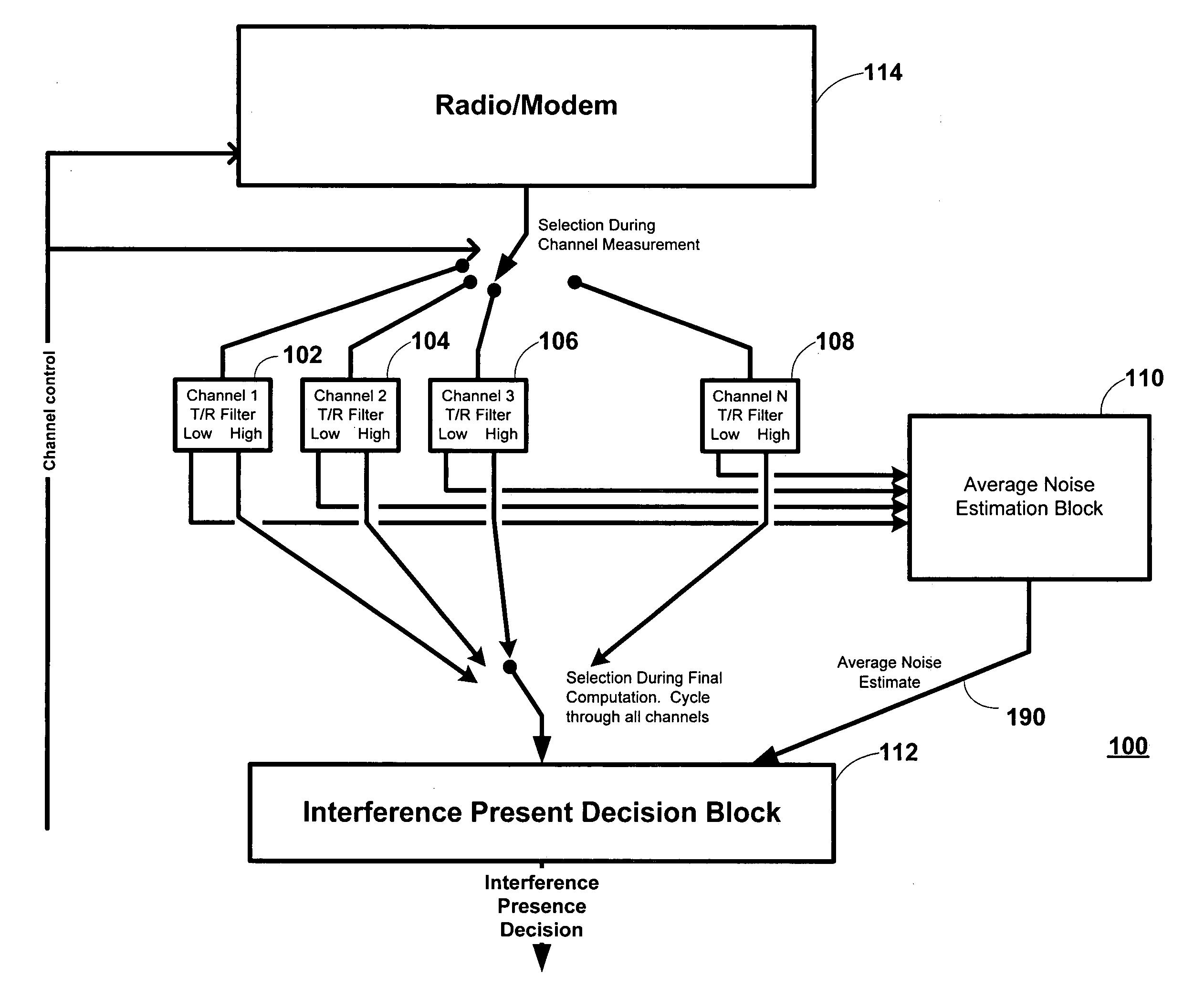
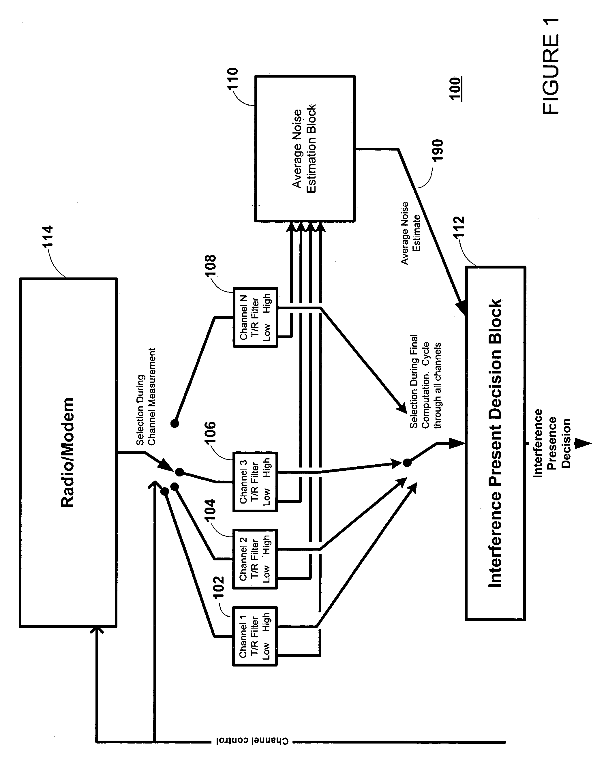
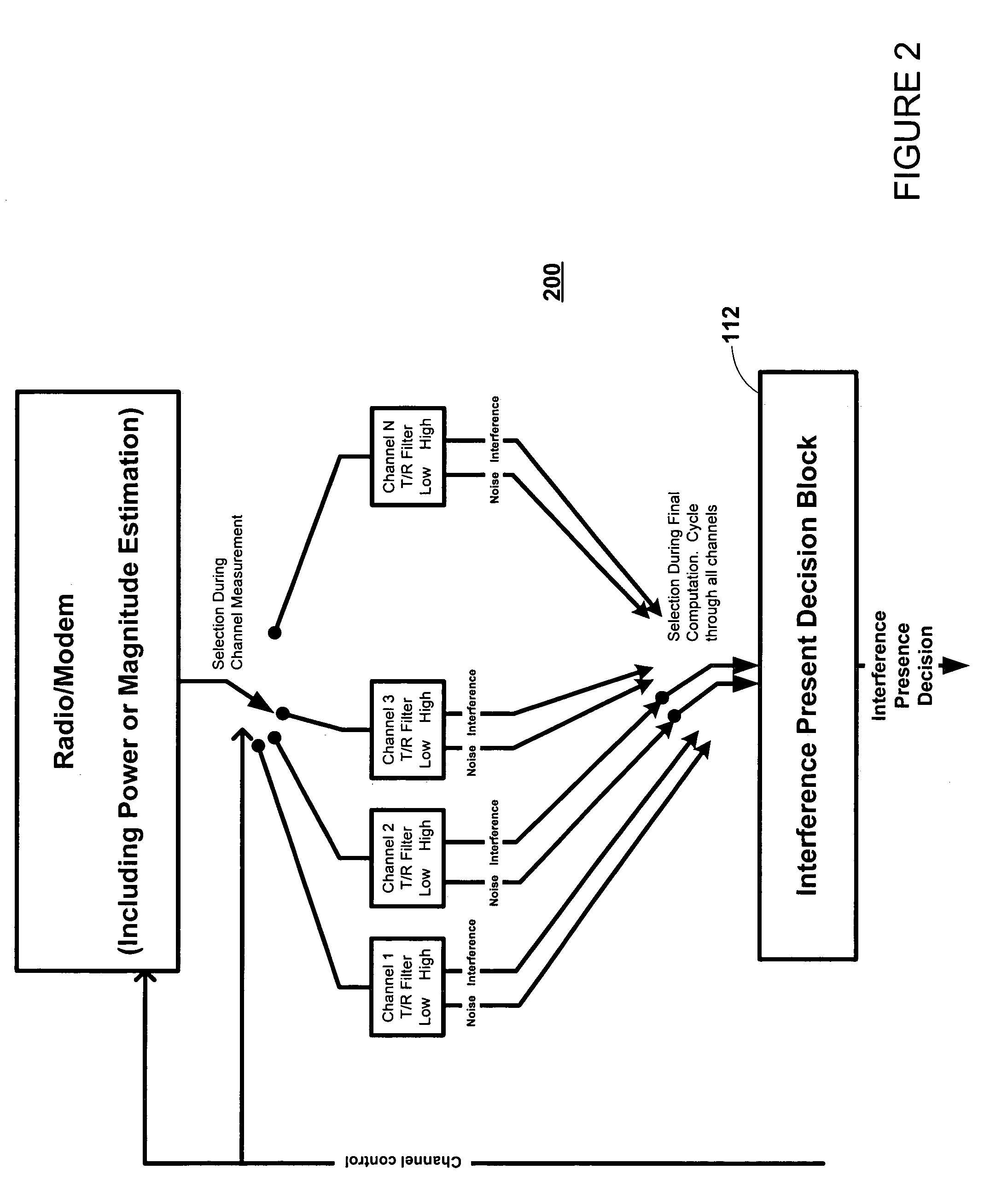
[0031]FIGS. 1 and 2 are simplified high-level block diagrams showing interference estimation apparatus made in accordance with the present invention. As shown in FIG. 1, in one embodiment, the inventive interference estimation apparatus 100 includes a plurality of tracking register (T / R) filter blocks for each channel- to be monitored by the apparatus 100 (e.g., Channel 1 T / R filter 102, T / R filter 104, etc). As described below in more detail, the T / R filter blocks measure noise and interference levels for each associated and corresponding data channel. Each T / R filter block includes both a “high” T / R filter that tracks the interference in the associated channel and a “low” T / R filter that track...


PUM


Abstract

A method and apparatus for estimating the presence of RF interference in a wireless data channel is described. The method and apparatus comprises a set of identical tracking / register (T / R) filter blocks, each T / R filter block associated and corresponding to an RF channel of interest. Each T / R filter block includes a pair of tracking / register (T / R) filters. Power / magnitude estimates from an RSSI calculation are input to the T / R filter blocks. One T / R filter is used to estimate the noise floor (in the absence of interference). The T / R filter latches and filters the lowest input values received from a power / magnitude circuit. The other T / R filter estimates the level of an interferer, if present, by latching and filtering the largest valued outputs of the power / magnitude circuit.

Description

CROSS-REFERENCE TO-RELATED APPLICATIONS[0001]This invention is related to commonly-assigned co-pending application Ser. No. 10 / 216,082, filed Aug. 8th, 2002, entitled “Method and Apparatus for a Dual-Mode Radio in a Wireless Communication System”; and commonly-assigned co-pending application Ser. No. 10 / 235,090, filed Sep. 3rd, 2002, entitled “Method and Apparatus Implementing an Overlay Adaptive Frequency Hopping Kernel in a Wireless Communication System”. Both of the related applications are hereby incorporated by reference herein in their entirety and referred to hereafter as “the related applications”.BACKGROUND[0002]1. Field of the Invention[0003]This invention relates to the field of wireless communication systems, and more particularly to the field of detecting interference in wireless communication channels.[0004]2. Description of Related Art[0005]As is well known in the wireless data communications arts, a common trade-off in the design of communication systems is performan...

Claims


Application Information

Patent Timeline
Patent Type & Authority Patents(United States)
IPC IPC(8): H04B1/00
CPCH04B17/318H04B1/1027
Inventor HALL, STEVEN DEANE
Owner QUALCOMM INC
Learn More