
Decoding error-correcting codes based on finite geometries

a code and error correction technology, applied in the field of error correction codes for data storage and data transmission, can solve the problems of bounded-distance decoders failing to correctly decode transmitted code-words, storage media, and difficulty in decoding corrupted messages

Inactive Publication Date: 2006-09-05
MITSUBISHI ELECTRIC INFORMATION TECH CENT AMERICA ITA
View PDF7 Cites 21 Cited by
  • Summary
  • Abstract
  • Description
  • Claims
  • Application Information

AI Technical Summary

Benefits of technology

"The present invention provides a method for decoding a (N, k) finite geometry code. The method involves representing the code using a parity check matrix, storing received words in a register, and iterating through a decoding cycle to determine the code's contents. The method can output a code-word if the termination condition is satisfied. The technical effect of this invention is to provide a more efficient and accurate method for decoding finite geometry codes."

Problems solved by technology

A fundamental problem in the field of data storage and communication is the development of practical decoding methods for error-correcting codes (ECC), see Blahut, “Algebraic Codes for Data Transmission,” Cambridge University Press: Cambridge, 2003, and MacWilliams et al., “The Theory of Error-Correcting Codes,” North-Holland: New York, N.Y., 1977.
Corruption can be caused by failure in the storage media or noise in the transmission channel.
However, as the size of the parameters N and k increases, so does the difficulty of decoding corrupted messages.
Conversely, a bounded-distance decoder fails to decode when the received word has a distance from any code-word that is greater than the decoding radius t. If the channel introduces t or more bit flips, then the bounded-distance decoder fails to correctly decode the transmitted code-word.
The error-correcting performance of a bounded-distance decoder is normally much worse than the performance of an optimal, “maximum-likelihood” decoder.
Unfortunately, the complexity of true maximum-likelihood decoders increases exponentially with the number of information bits k, making them impractical for codes with a reasonably large number of information bits.
In contrast to codes based on finite geometries, it is normally impractical to even compute the distance d, for a given LDPC code.
The fact that bit-flipping decoders are not bounded-distance decoders means that there is no guarantee that is possible to decode a received word even if it is only corrupted by t or fewer bit flips.
Although Reed-Muller codes date from 1954, and bit-flipping decoders for LDPC codes date from the early 1960's, nobody has previously devised a way to use a bit-flipping decoder for Reed-Muller codes or other finite geometry codes.

Method used


Image

  • Decoding error-correcting codes based on finite geometries
  • Decoding error-correcting codes based on finite geometries
  • Decoding error-correcting codes based on finite geometries

Examples


Embodiment Construction

[0075]Defining a Parity Check Matrix Representation for the Code

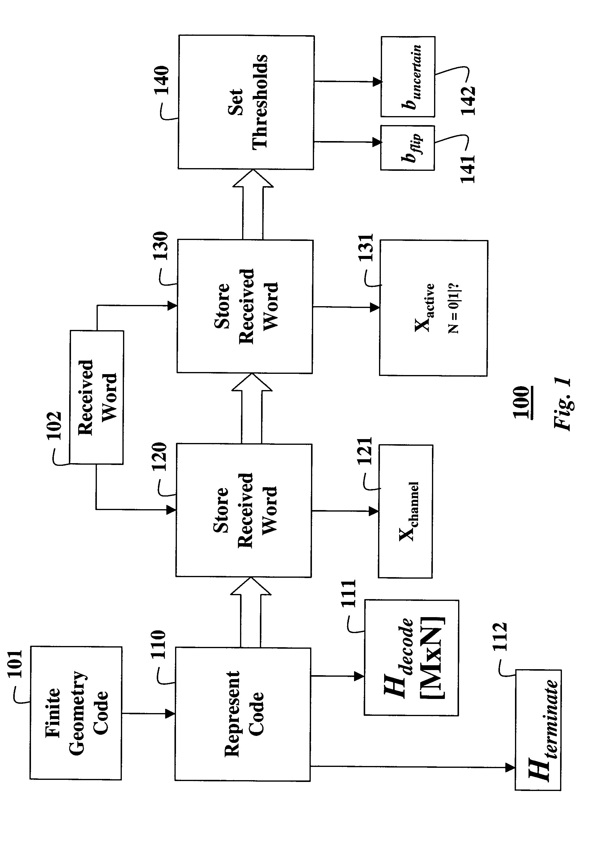
[0076]FIGS. 1 and 2 shows steps of a method for decoding an error-correcting code based on a finite geometry according to our invention. The code has a block-length N and a dimension k. The code is based on a finite geometry with a given number of points N and a given number of μ-flats, as known in the art.

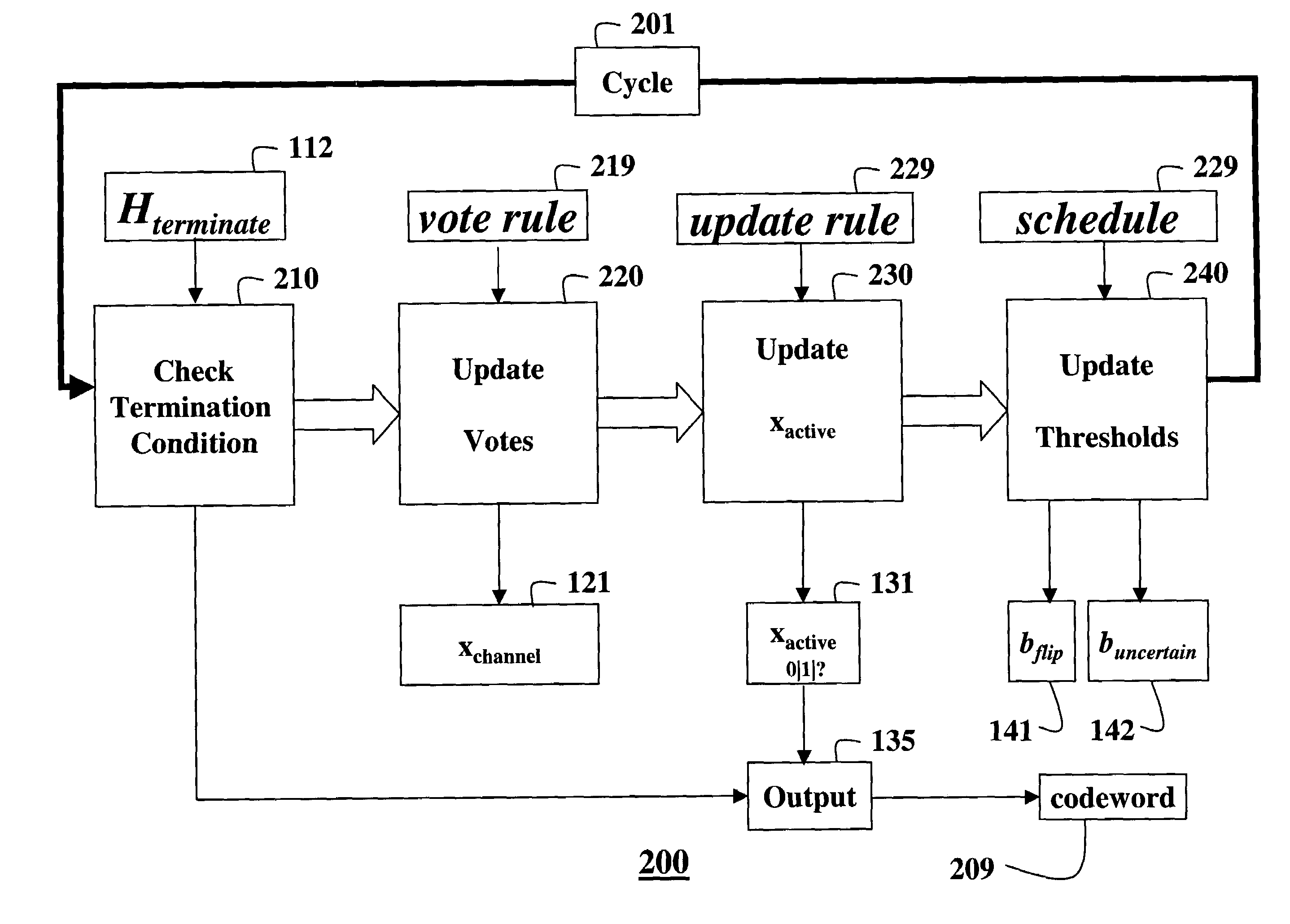
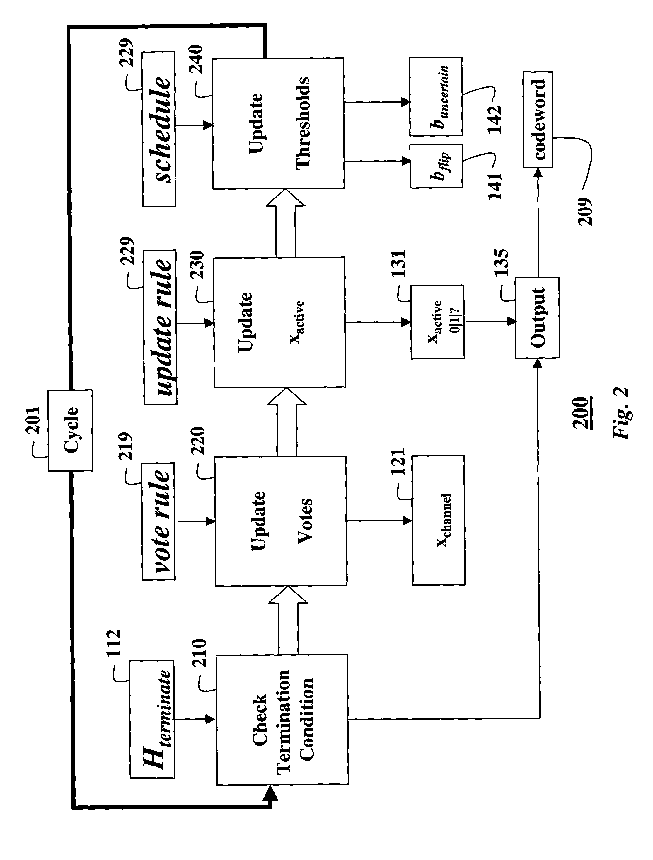
[0077]FIG. 1 shows a one-time initialization procedure 100, and FIG. 2 shows the step of an iterative decoding procedure 200.

[0078]Initialization

[0079]More precisely, we define the code 101 by a decoding parity check matrix (Hdecode) 111 whose M rows are incidence vectors of a sub-set of μ-flats in the finite geometry with respect to the points in the finite geometry.

[0080]We define the M by N parity check matrix by selecting a sub-set of the μ-flats in the finite geometry, and using their incidence vectors with respect to the points of the finite geometry as the rows of our parity check matrix 111. We call this parit...


PUM


Abstract

A method decodes a received word for a binary linear block code based on a finite geometry. First, a parity check matrix representation of the code is defined. The received word is stored in a channel register. An active register represents a current state of the decoder. Each element in the active register can take three states, representing the two possible states of the corresponding bit in the word, and a third state representing uncertainty. Votes from parity checks to elements of the active register are determined from parity checks in the matrix, and the current state of the active register. A recommendation and strength of recommendation for each element in the active register is determined from the votes. The elements in the active register are then updated by comparing the recommendation and strength of recommendation with two thresholds, and the state of the corresponding bit in the received word. When termination conditions are satisfied, the decoder outputs the state of the active register. If the decoder outputs a state of the active register that does not correspond to a codeword, a new representation for the code using a parity check matrix with substantially more rows is chosen, and the decoding cycle is restarted.

Description

FIELD OF THE INVENTION[0001]The present invention relates generally to the field of error-correcting codes for data storage and data transmission, and more particularly to a decoding method for a class of error-correcting codes based on finite geometries.BACKGROUND OF THE INVENTION[0002]A fundamental problem in the field of data storage and communication is the development of practical decoding methods for error-correcting codes (ECC), see Blahut, “Algebraic Codes for Data Transmission,” Cambridge University Press: Cambridge, 2003, and MacWilliams et al., “The Theory of Error-Correcting Codes,” North-Holland: New York, N.Y., 1977.BINARY LINEAR BLOCK ERROR-CORRECTING CODES[0003]Any references to “codes” herein specifically mean binary linear block error-correcting codes. The basic idea behind these codes is to encode messages of k information bits using blocks of N bits, where N>k. The additional N−k bits are used to decode and correct corrupted messages. A block of N bits is also...

Claims


Application Information

Patent Timeline
Patent Type & Authority Patents(United States)
IPC IPC(8): H03M13/43H03M13/45G06F11/10G06F11/00H03M13/00H03M13/09H03M13/19H03M13/37
CPCH03M13/134H03M13/3746H03M13/3738H03M13/136
Inventor YEDIDIA, JONATHAN S.FOSSORIER, MARC P. C.PALANKI, RAVI
Owner MITSUBISHI ELECTRIC INFORMATION TECH CENT AMERICA ITA
Learn More