Pinch valve

a technology of pinch valve and spherical valve, which is applied in the direction of diaphragm valve, engine diaphragm, machine/engine, etc., can solve the problems of inacceptable wafers, altering or removing critical wafer structures, and bio-technology fluid control problems, so as to reduce errors

Active Publication Date: 2006-09-12
EMERSON ELECTRIC CO
View PDF22 Cites 67 Cited by
  • Summary
  • Abstract
  • Description
  • Claims
  • Application Information

AI Technical Summary

Benefits of technology

[0018]A controller receives a measurement output signal from the flow measurement device and provides a control output signal to the pinch valve in response to a setpoint signal and the measurement output signal to adjust the pinch member relative to the reference surface to control fluid flow through the flow tube as necessary to reduce any error between the measured flow and the setpoint flow. In certain embodiments, the flow measurement device is a Coriolis mass flow measurement device.

Problems solved by technology

Many industries such as semiconductor, pharmaceutical, and bio-technology experience fluid control problems due to the typically low flow rates, the use of abrasive chemical fluids, the use of corrosive chemical fluids, and the need for contaminant free, accurate, compact, and real-time fluid control and delivery systems.
Over-polishing the wafer can result in altering or removing critical wafer structures.
Conversely, under-polishing of the wafer can result in unacceptable wafers.
The key difference between the lithography process and the spin-on deposition is that any defect in the film (such as a void, bubble or particle) is now permanently embedded in the structure of the semiconductor and could result in non-functioning devices and a financial loss for the semiconductor producer.
Even if the sliding parts are made up of low friction materials, there will still be some friction.
This friction can result in a stick-slip motion of the pinch valve, impacting the precision of flow control.

Method used


Image

  • Pinch valve
  • Pinch valve
  • Pinch valve

Examples


Embodiment Construction

[0033]Illustrative embodiments of the invention are described below. In the interest of clarity, not all features of an actual implementation are described in this specification. It will of course be appreciated that in the development of any such actual embodiment, numerous implementation-specific decisions must be made to achieve the developers specific goals, such as compliance with system-related and business-related constraints, which will vary from one implementation to another. Moreover, it will be appreciated that such a development effort might be complex and time-consuming, but would nevertheless be a routine undertaking for those of ordinary skill in the art having the benefit of this disclosure.

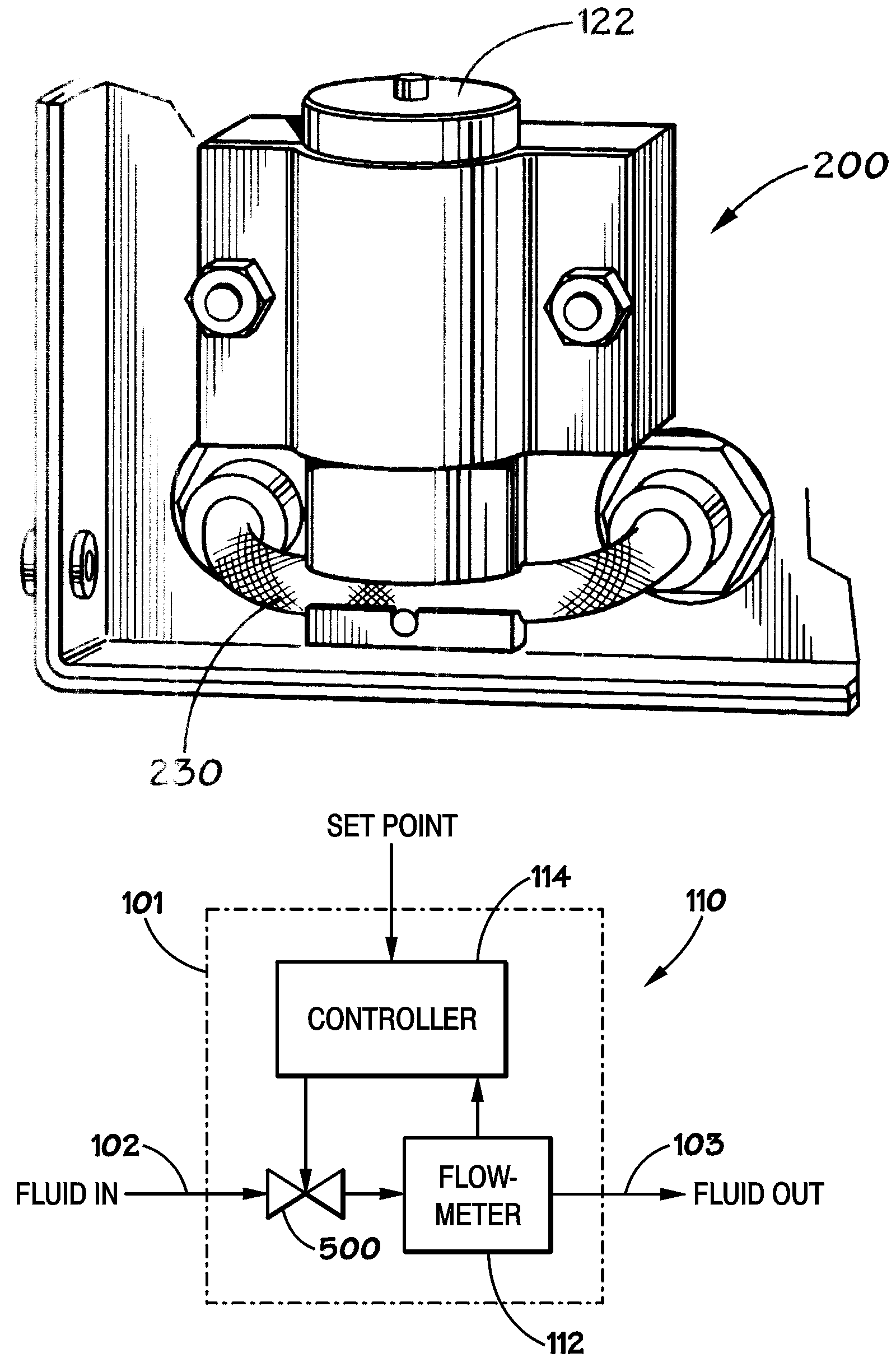
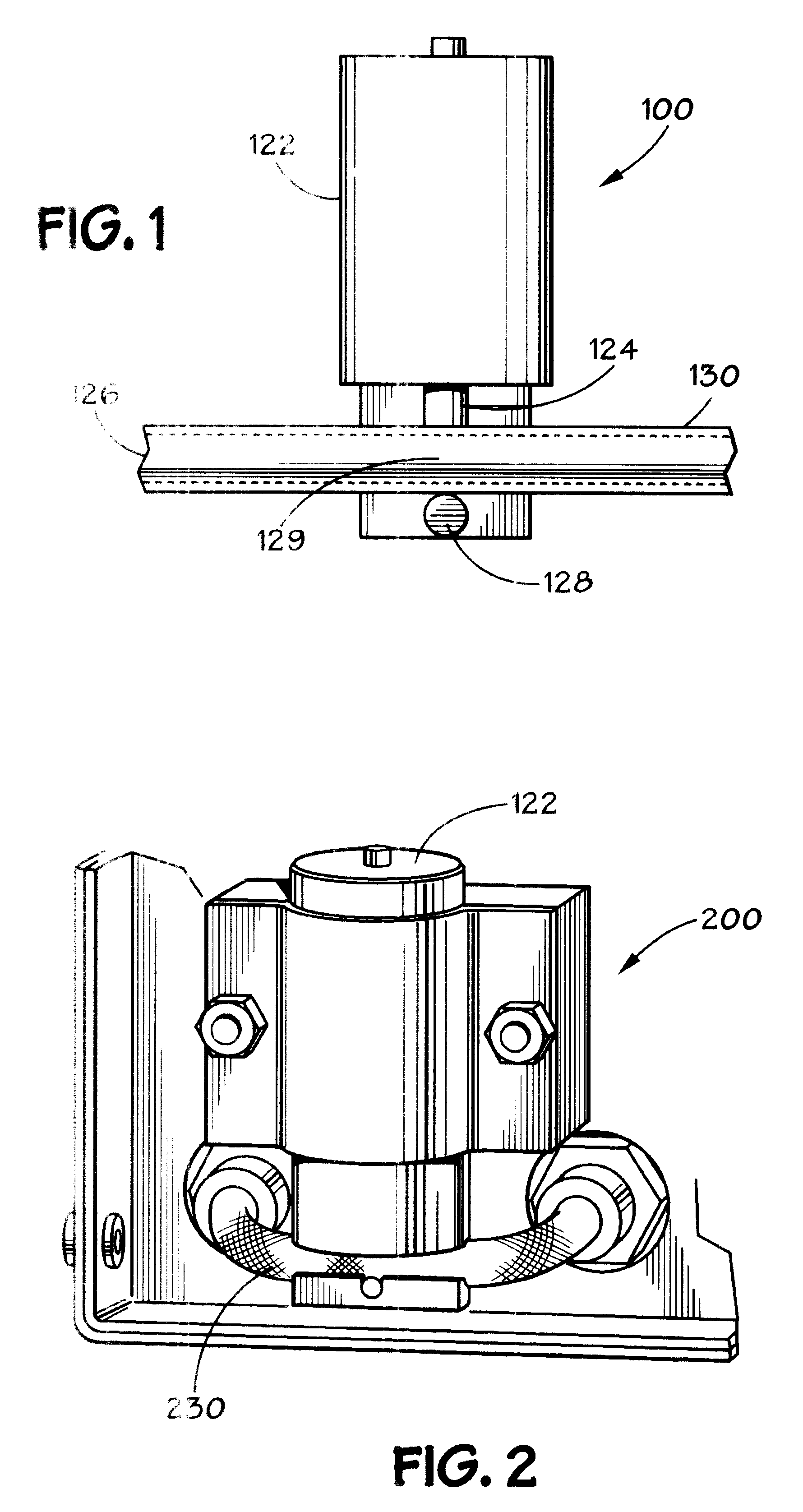
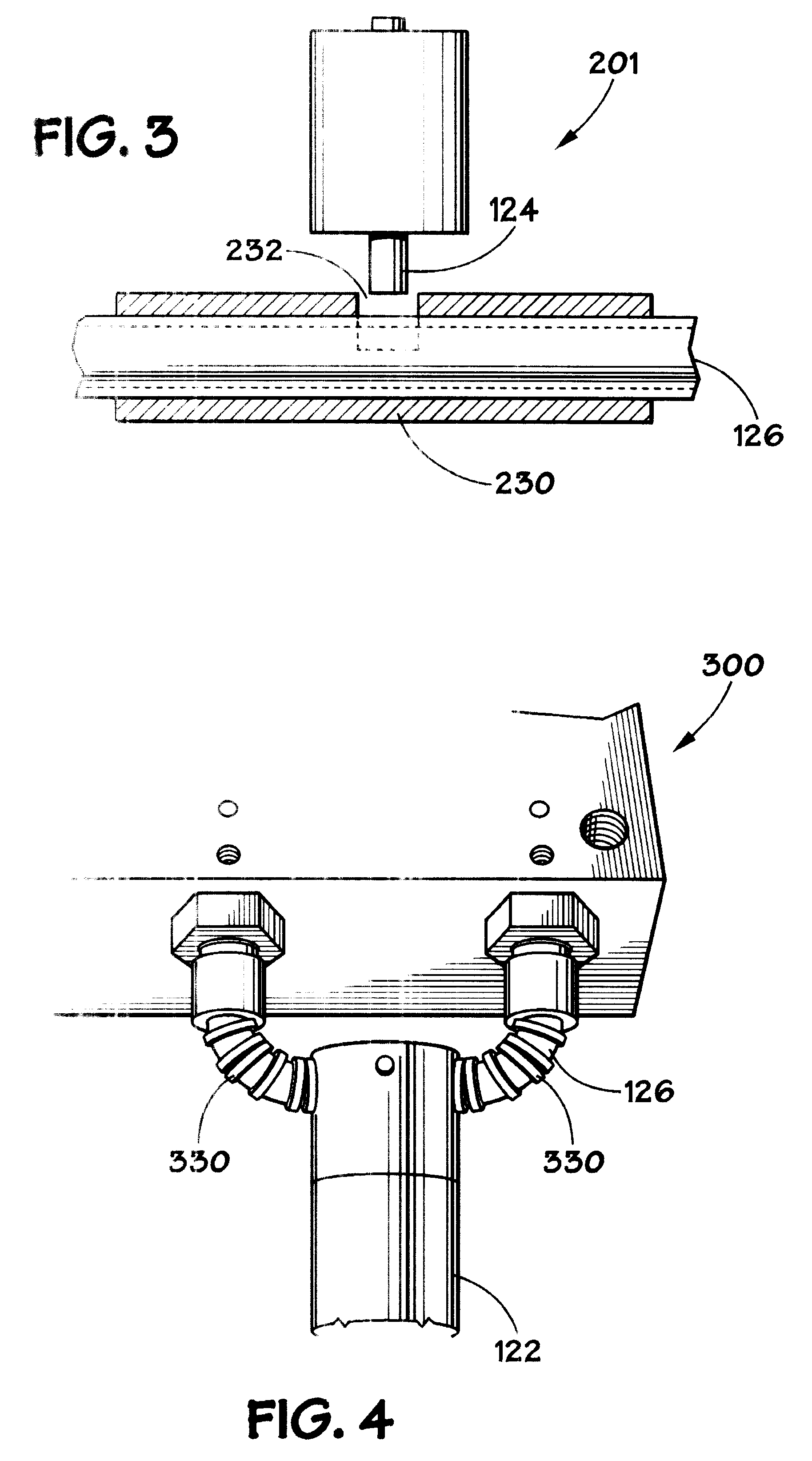
[0034]A pinch valve 100 in accordance with an embodiment of the present invention is conceptually illustrated in FIG. 1. An actuator 122 is situated next to an elastomeric tube 126. A valve plunger 124, which may be in the form of a piston or ram, is moved by the actuator 122 to s...


PUM


Abstract

A control valve includes an elastomeric flow tube, a plunger having first and second ends, and a pinch member connected to the first end of the plunger. The pinch member is situated adjacent the flow tube. A reference surface is positioned generally opposite the pinch member such that the elastomeric tube is squeezable between the pinch member and the reference surface to control fluid flow through the flow tube. A first guide spring is situated between the pinch member and the first end of the plunger, and a second guide spring is situated adjacent the second end of the plunger. A damper may be connected to the plunger. Further, a pressure containing member may situated about at least a portion of the flow tube.

Description

CROSS REFERENCE TO RELATED APPLICATIONS[0001]This application is a continuation-in-part of International Patent Application No. PCT / US03 / 09381, filed Mar. 28, 2003, which designates the United States of America and claims priority to U.S. Provisional Patent Application No. 60 / 369,493, filed Apr. 1, 2002. Both of these applications are incorporated by reference.BACKGROUND OF THE DISCLOSURE[0002]1. Field of the Disclosure[0003]The present invention relates generally to fluid flow and control, and more particularly, to a pinch valve having a reduced-friction guide mechanism.[0004]2. Description of Related Art[0005]A fluid flow control system generally consists of three components: a flow sensor, a control valve and a controller such as a proportional-integral-derivative (PID) controller. A typical fluid flow control system functions by changing the amount of opening of the control valve until the flow sensed by the flow sensor matches the desired, or set point flow. Often, the control ...

Claims


Application Information

Patent Timeline
Patent Type & Authority Patents(United States)
IPC IPC(8): G05D7/06F16K7/06F16K7/04
CPCF16K7/045Y10T137/7759Y10T137/7761F16K31/0651H01L21/02
Inventor DILLE, JOSEPH C
Owner EMERSON ELECTRIC CO
Why Eureka
Try Eureka