Electronic equipment mounting angle varying apparatus

a technology of mounting angle and varying apparatus, which is applied in the direction of instruments, machine supports, other domestic objects, etc., can solve the problems of high manufacturing cost, product not having the feel of high quality products, and user extra cost burden, and achieve the effect of low manufacturing cos

Inactive Publication Date: 2006-09-12
KK TOSHIBA
View PDF14 Cites 61 Cited by
  • Summary
  • Abstract
  • Description
  • Claims
  • Application Information

AI Technical Summary

Benefits of technology

[0041]In view of the situation described in the foregoing, an object of the present invention is to provide an electronic equipment mounting angle varying apparatus of low manufacturing cost that is attachable and detachable to and from the electronic equipment.

Problems solved by technology

Now, the telephone set mounting angle varying apparatuses described in the foregoing are configured integrally beforehand with the telephone main bodies, and constitute an extra cost burden to a user who does not need a mounting angle varying apparatus.
In the mounting angle varying apparatuses 130, 140, and 150 shown in FIG. 41 to 52, similarly, when changing the angle of the telephone main body, the telephone main body portion separates from the telephone base, and there is a problem in that the product does not have the feel of a high quality product.
With the mounting angle varying apparatuses described in the foregoing, furthermore, the structure is complex and die equipment costs are high, and most of the apparatuses are not easy to assemble, making them problematic in terms of escalating manufacturing costs.
In addition, when an add-on module (see FIG. 33) is attached to the telephone set, with only the mounting angle varying apparatuses described in the foregoing the balance becomes poor and stability is lacking.
When a mounting angle varying apparatus made specifically for the add-on module is additionally installed, moreover, the number of parts and the die equipment costs increase, leading to escalating manufacturing costs.

Method used


Image

  • Electronic equipment mounting angle varying apparatus
  • Electronic equipment mounting angle varying apparatus
  • Electronic equipment mounting angle varying apparatus

Examples


first embodiment

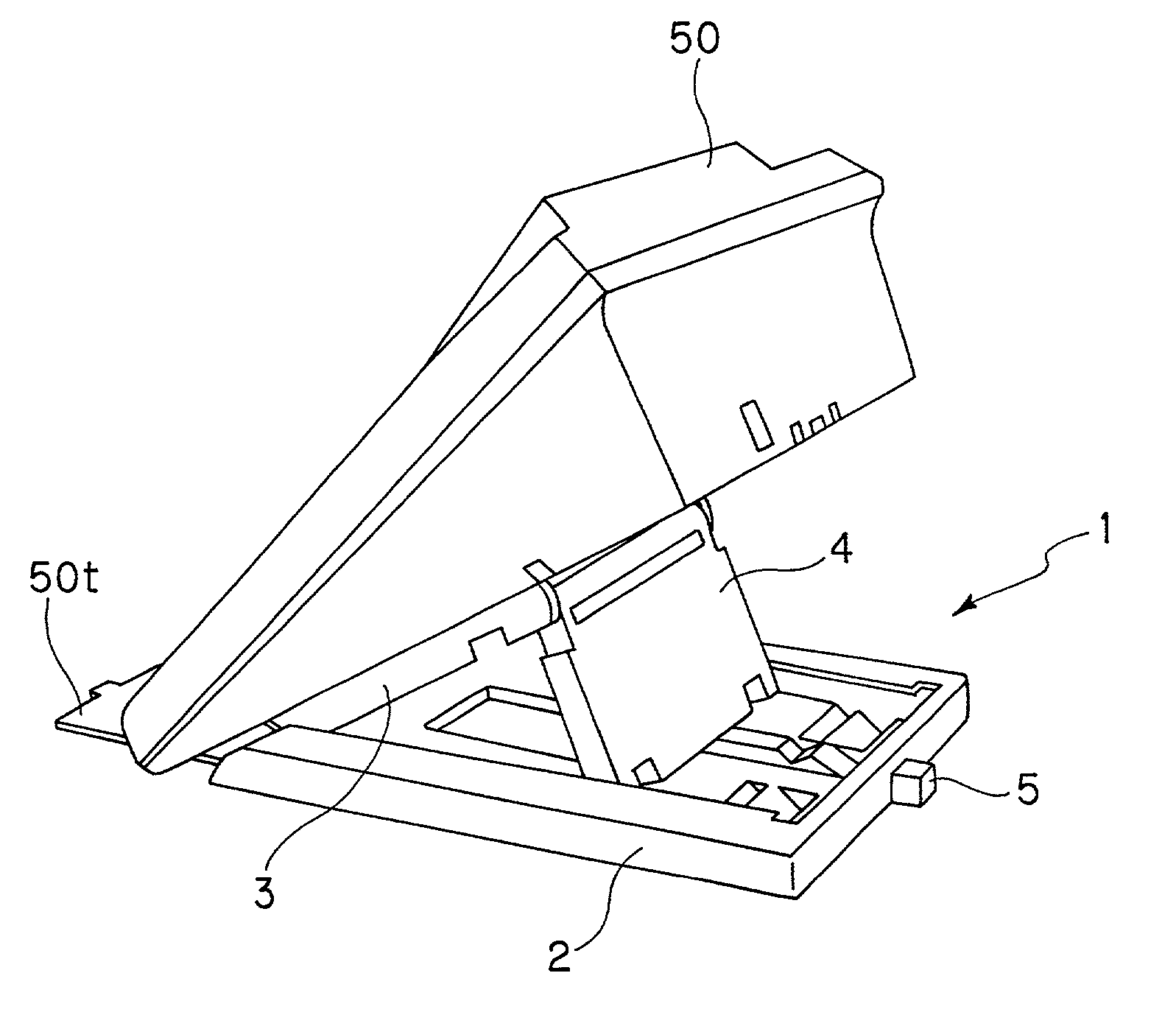
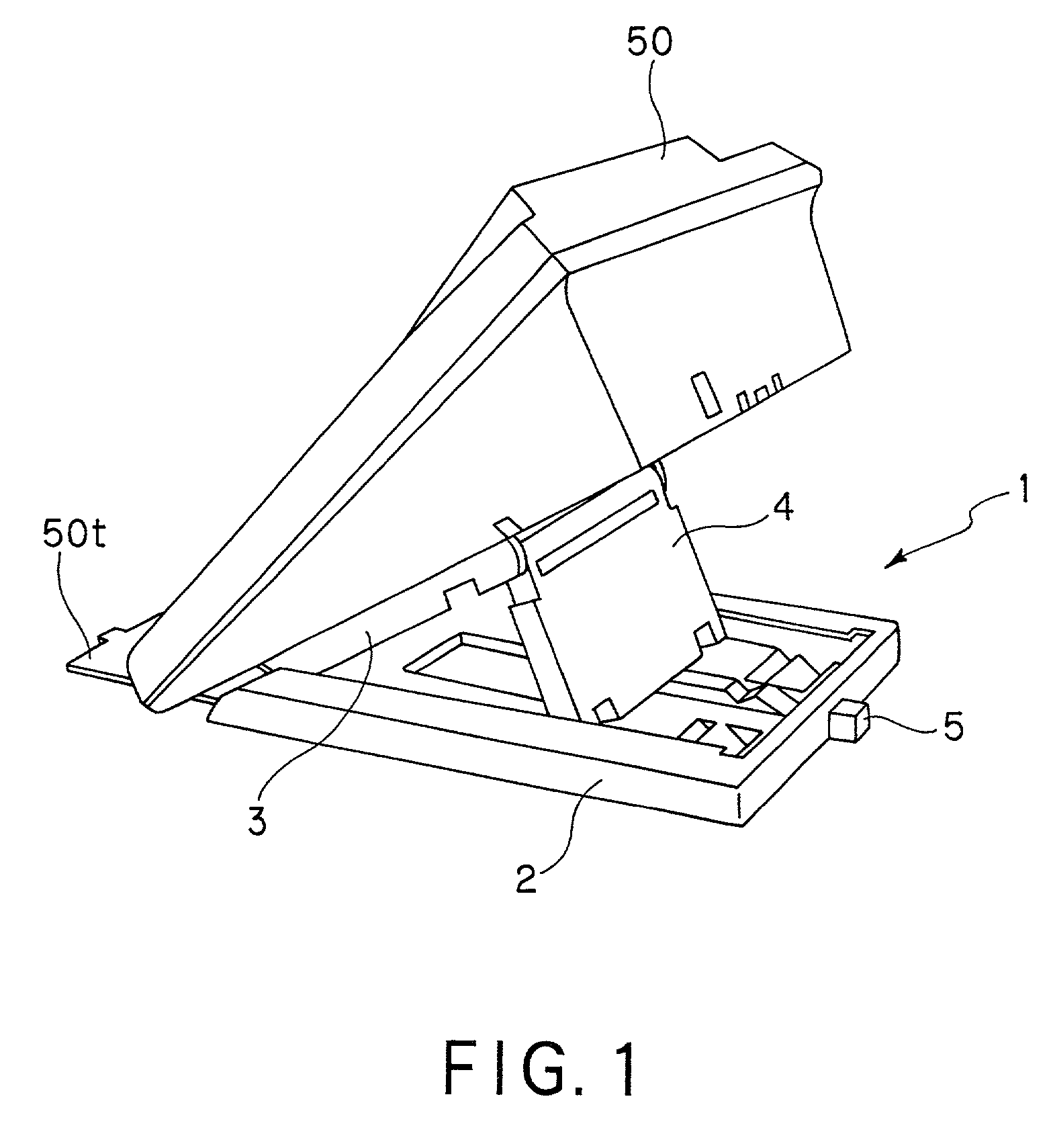
[0112]Referring to FIG. 1, a mounting angle varying apparatus 1 for a telephone set 50 that is electronic equipment, to which the present invention is applied, comprises a tilt base (base unit) 2 forming a mounting surface, a tilt cover (mounting unit) 3 attached to the lower surface of the telephone set 50, a tilt arm (arm unit) 4 attached to the tilt cover 3 in a turnable fashion and latched to the tilt base 2, and a tilt button (operating unit) 5 that is pressed when the mounting angle of the telephone set 50 is altered are comprised.

[0113]Also, a telephone number card affixing tray 50t that is attached to the lower surface of the telephone set 50 when the mounting angle varying apparatus 1 is not installed in the telephone set 50 is attached to the lower surface of the tilt base 2 of the mounting angle varying apparatus 1 when the mounting angle varying apparatus 1 is installed in the telephone set 50.

[0114]The angle varying apparatus 1 is attached such that it engages guide rai...

second embodiment

[0275]A description is given next of a second embodiment that comprises a tilt base (base unit) 2′ and tilt button (operating unit) 5′ wherewith it is possible to perform the attachment of the tilt button to the tilt base and the detachment of the tilt button from the tilt base simply.

[0276]The second embodiment is of exactly the same configuration as the first embodiment except for the configuration related to the assembly of the tilt base 2 and the tilt button 5 of the first embodiment, and the first embodiment is applied in the same manner.

[0277]The tilt button 5′ has substantially the same configuration as the tilt button 5 of the first embodiment, as noted above; configuration that is the same is indicated by the symbols of the first embodiment, and no further description thereof is given here.

[0278]As shown in FIG. 29, in a front wall panel 5h′ that forms the end of the tilt button 5′ in the longitudinal direction on the side of the sloping guide surface 5a3 is formed an abutt...

third embodiment

[0319]A description is given next of a mounting angle varying apparatus that is a third embodiment, for altering the mounting angle when an add-on module (auxiliary equipment) 51 has been installed to the telephone set 50 in order to add extension lines or the like, as shown in FIG. 31.

[0320]As shown in FIG. 34, in order to change the mounting angle of the telephone set 50 to which the add-on module 51 has been added, two mounting angle varying apparatuses 10 are used.

[0321]The mounting angle varying apparatus 10, as shown in FIG. 33, has, in the upper surface of the telephone set attachment panel 3p of the tilt cover 3 in the mounting angle varying apparatus 1 described earlier, a predetermined number of attachment hubs 13b disposed with apparatus attachment holes 13ba made therein, passing vertically through the telephone set attachment panel 3p.

[0322]A tilt base 12, as shown in FIG. 34, has the same configuration as the tilt base 2 (standard base unit) (see FIG. 34(a)) in the mo...


PUM


Abstract

An electronic equipment mounting angle varying apparatus comprises a base member mounted at a place where electronic equipment is installed; a mounting member on which the electronic equipment is mounted, and which is supported by the base member so as to freely swing about a horizontal base support shaft axis; and an arm member supported by the mounting member so as to freely swing about a mounting member support shaft axis extending horizontally, which sets mounting angle of the electronic equipment by being latched by the base member, whereby the electronic equipment is mounted at a prescribed angle.

Description

CROSS REFERENCE TO RELATED APPLICATIONS[0001]This application is based upon and claims the benefit of priority from the prior Japanese Patent Application No. 2001-2808 filed on Jan. 10, 2001 and Japanese Patent Application No. 2001-191410 filed on Jun. 25, 2001; the entire contents of these prior applications being incorporated herein by reference.BACKGROUND OF THE INVENTION[0002]1. Field of the Invention[0003]This invention relates to an electronic equipment mounting angle varying apparatus for setting electronic equipment at a desired angle.[0004]2. Description of the Related Art[0005]Referring to FIG. 48, conventionally, there has been a mounting angle varying apparatus 110 for electronic equipment such as telephone sets, which turn a telephone main body 111 relative to a telephone base 112 and set the telephone set at one of two angles.[0006]This mounting angle varying apparatus 110 is such that, with the telephone main body 111 disposed so that it turns freely relative to the t...

Claims


Application Information

Patent Timeline
Patent Type & Authority Patents(United States)
IPC IPC(8): F16M11/00F16M11/10G01D11/30H04M1/11
CPCF16M11/10H04M1/11G01D11/30F16M2200/024
Inventor UTO, YOSHIHIROYOSHIDA, SHINICHIHOSHINO, TSUTOMU
Owner KK TOSHIBA
Why Eureka
Try Eureka