
Printing method and printer with failure compensation

a printing method and printer technology, applied in printing, other printing apparatus, etc., can solve the problems of incomplete nozzle failure compensation and impaired image quality, and achieve the effect of avoiding complete information loss, increasing segmentation process sensitivity, and high level of high-frequency contras

Inactive Publication Date: 2006-09-12
OCE TECH
View PDF8 Cites 7 Cited by
  • Summary
  • Abstract
  • Description
  • Claims
  • Application Information

AI Technical Summary

Benefits of technology

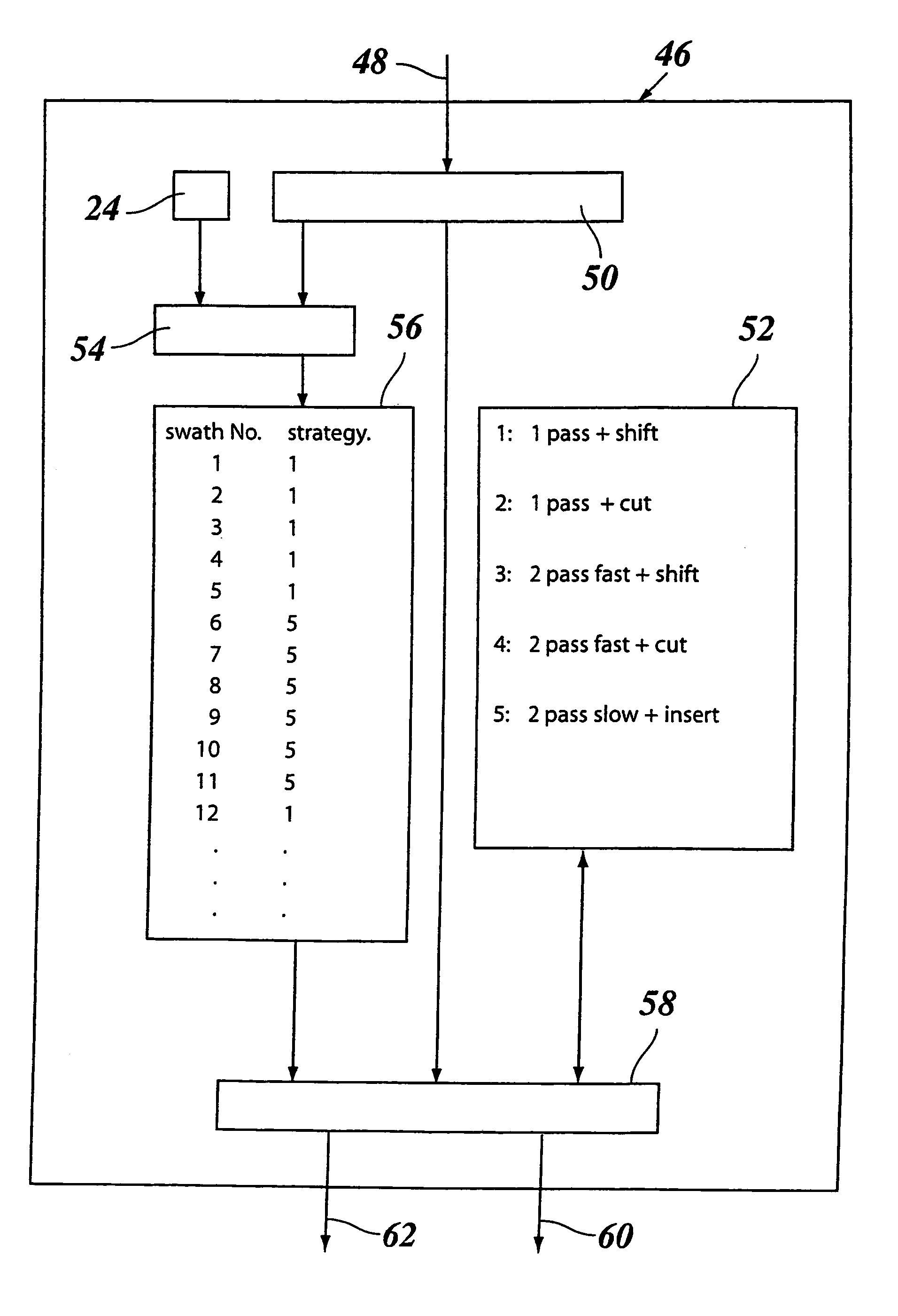
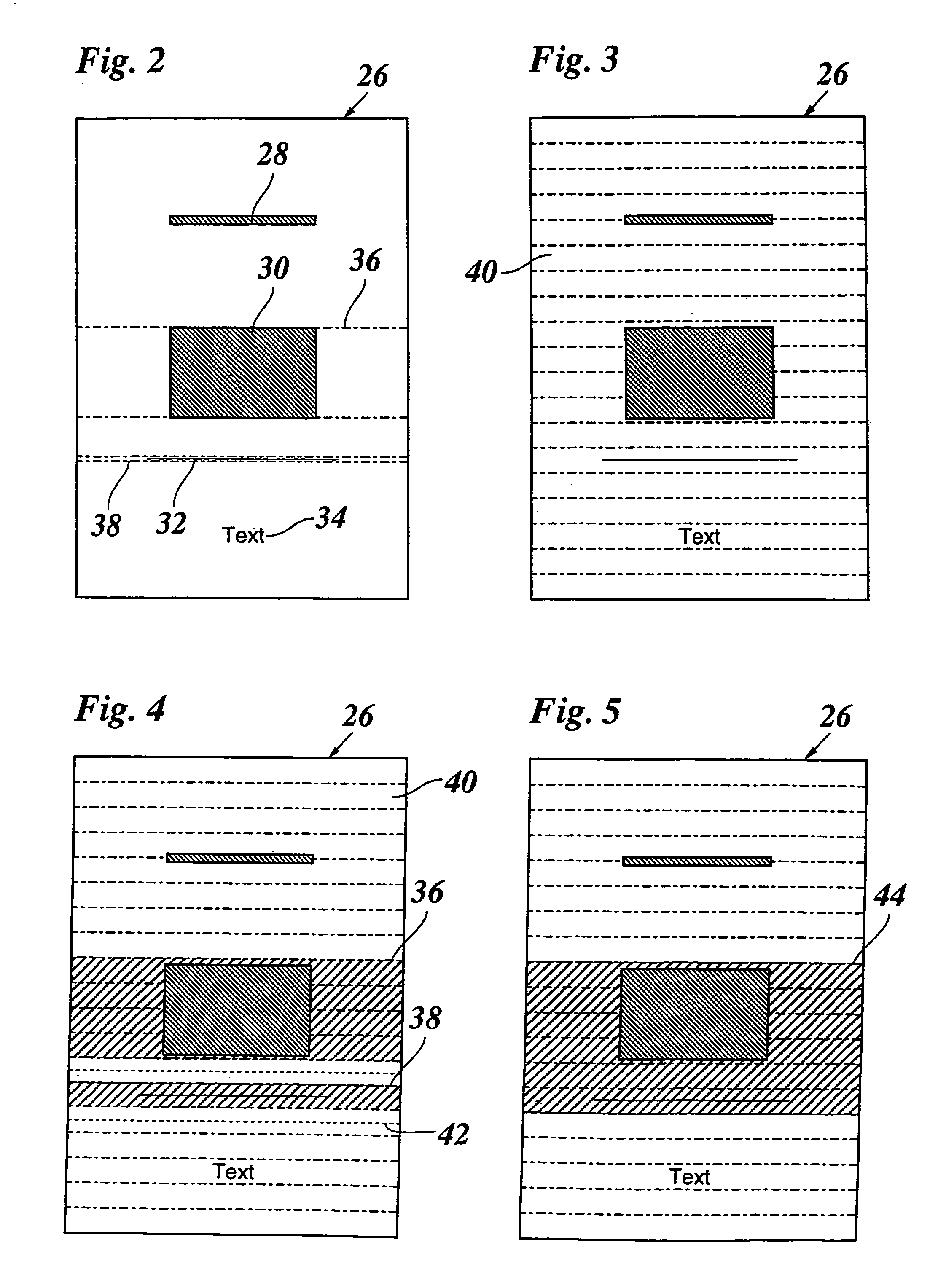
[0017]For example, the shift-type failure compensation strategy disclosed in EP-A-1 060 896, in which the black pixels that cannot be printed are shifted to neighboring locations, will be most suitable for relatively bright image areas, i.e. image areas in which the density of black pixels is comparatively low, so that a sufficient number of white pixel locations is available to which the black pixels may be shifted. In contrast, in a relatively dark image area, e.g. a solid black area, this compensation strategy is likely to lead to a visible defect in the printed image. In order to achieve a high image quality in such dark image areas, it would therefore be preferable to adopt one of the other failure compensation strategies discussed above which are capable of fully compensating the defect but which will generally lead to certain losses in productivity. It is a main advantage of the present invention that, when a page to be printed contains both, dark and bright image areas, it is not necessary to use a relatively slow failure compensation strategy, which assures a good image quality in the dark areas, for the whole page, but it is possible to use this slower strategy only where it is actually needed, whereas other parts of the page, i.e. the bright image areas, can be printed with a more productive failure compensation strategy which nevertheless provides a sufficient image quality in these areas. As a result, it is possible to achieve a satisfactory image quality and nevertheless to increase the overall productivity of the print operation.
[0018]Although it would be feasible to change the failure compensation strategy even within a single stroke of the printhead, it will generally be more efficient to retain one and the same compensation strategy for a complete printhead stroke. Thus, the segments identified in the segmentation process will preferably consist of swaths or bands that extend over the whole width of the page and correspond to an integral number of strokes of the printhead. Then, the part of the segment that is most sensitive to failure of a print unit will determine the compensation strategy to be adopted.
[0019]In a preferred embodiment, the printer comprises a failure detection system which automatically detects failures of print units, so that appropriate failure compensation strategies may be activated automatically. Failure detection and compensation may even be performed “on the fly”, i.e. while the printer is operating. Then, when a nozzle failure occurs at a time when the printer has printed a part of a page, the failure compensation unit will be activated immediately, so that the printer can continue with printing average number of black pixels contained in a given basic area. The minimum requirement for image quality and hence the failure compensation strategy to be applied may then be determined simply by setting threshold values to which the primary image classifiers are compared. In order to increase the sensitivity of the segmentation process, there may be provided a set of different primary image classifiers which differ from one another in the size of the basic area. Each classifier may then be compared to an associated threshold value, and the comparison results may be filtered with an appropriate filter in order to determine the ultimate compensation strategy.
[0020]It has been observed that a defect in the printed image, which defect may be the result of an incomplete failure compensation, is less perceptible to the human eye when there exists a high level of high-frequency contrast in the vicinity of the defect. In order to take advantage of this effect, it is preferable to employ a context filtering procedure in the segmentation process. The context filter may be applied to the primary classifiers or, alternatively, to the associated threshold values, e.g. by shifting the threshold values depending on the level of contrast in the basic area or the vicinity thereof.
[0021]The size of the segments determined in the segmentation process will naturally be adapted to the pattern of swaths printed by the printhead, i.e. the length of the nozzle array in the direction of paper transport. Since a frequent switching between different failure the rest of the page with failure compensation. Thus, visible defects in the printed image will only occur in the relatively short delay time between the detection of a nozzle failure and the time when the failure compensation unit becomes effective.
[0022]In some cases, however, even a short delay time between failure detection and failure compensation may lead to an unacceptable loss of image information. This is particularly the case when a thin horizontal line has to be printed, i.e. a line which extends in the scanning direction of the printhead and has a width of only a single pixel. Then, when the nozzle that is responsible for printing this pixel line becomes defective, the whole line will disappear. If, in that instant, the printer is in the single-pass mode, there will be no efficient way to compensate for this defect.

Problems solved by technology

If a nozzle of the printhead becomes clogged or fails for any other reason, the pixels that would have been printed with the inoperative nozzle will be missing in the printed image, and the image quality will be impaired.
This strategy helps to prevent loss of information but will not fully compensate the nozzle failure and is in many cases sufficient for suppressing the visual effect of the nozzle failure below acceptable limits.
In general, unless redundant nozzles are present in the printhead, failure compensation involves a tradeoff between productivity and image quality.

Method used


Image

  • Printing method and printer with failure compensation
  • Printing method and printer with failure compensation
  • Printing method and printer with failure compensation

Examples


Embodiment Construction

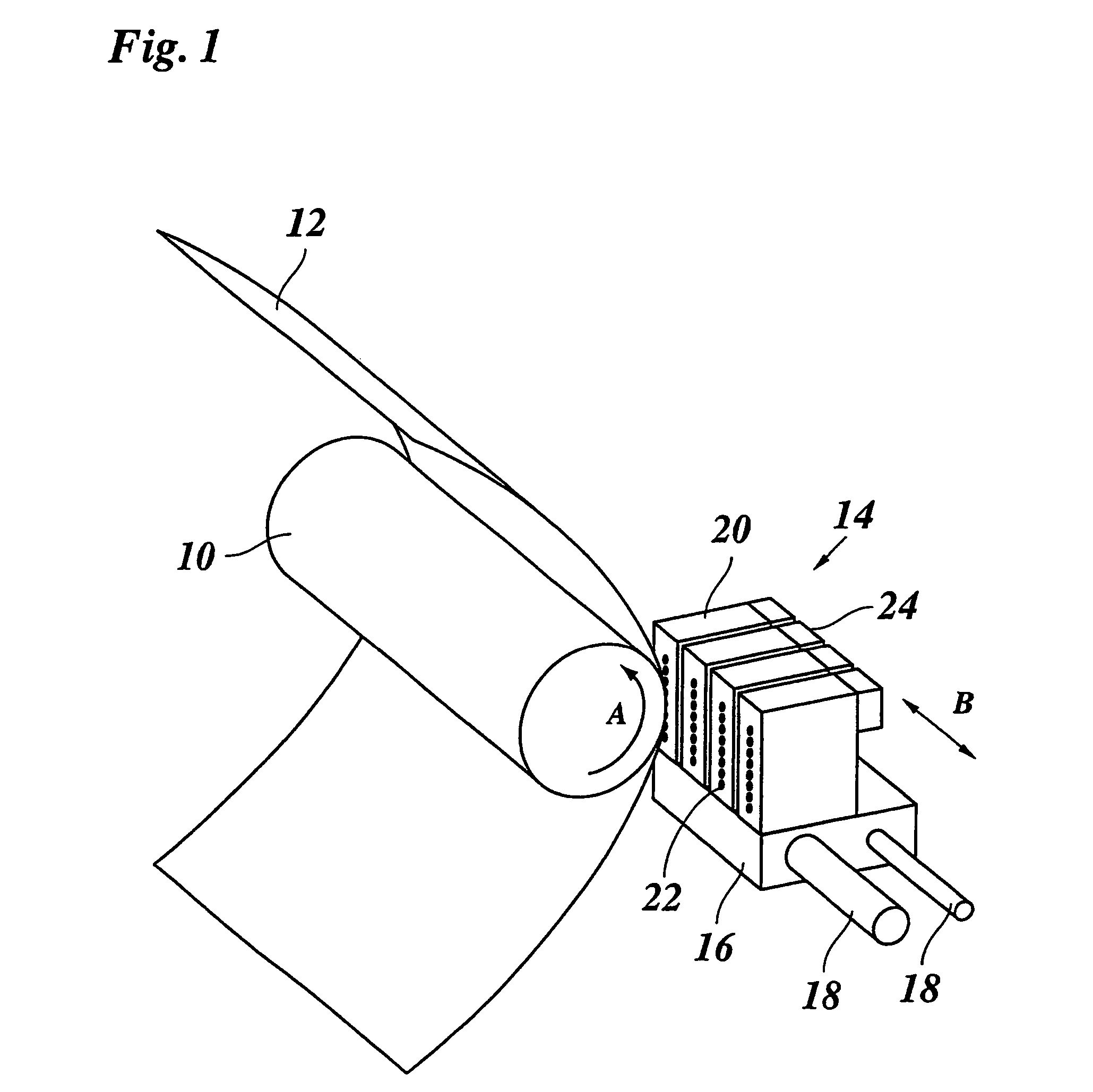
[0035]As is shown in FIG. 1, an ink jet printer comprises a platen 10 driven for rotation in the direction of an arrow A for transporting a paper sheet 12 which serves as an image recording medium. A printhead 14 is mounted on a carriage 16 which is guided on guide rails 18 and travels back and forth in the direction of an arrow B along the platen 10 so as to scan the paper sheet 12. The printhead 14 comprises four nozzle heads 20, one for each of the basic colors yellow, cyan, magenta and black. On the side facing the sheet 12, each nozzle head 20 has a linear array of nozzles 22. The nozzle heads 20 are energized in accordance with image information of an image to be printed on the sheet 12. Each nozzle 22 can be energized separately so as to eject an ink droplet which will form a dot at a corresponding pixel position on the sheet 12. Thus, when the printhead 14 performs a single stroke along the platen 10, each nozzle 22 can be energized to draw a single pixel line of the intende...


PUM


Abstract

A printer including a transport system for a recording medium, a printhead containing a plurality of print units each of which being capable of printing a pixel line when the printhead is scanned over the recording medium, and a failure compensation unit for controlling the print operation such that a failure of a print unit is compensated, wherein a segmentation unit is provided for dividing an image to be printed into segments containing different types of image information, and wherein the failure compensation unit includes a memory for storing a plurality of compensation strategies and a controller for selecting one of said compensation strategies in accordance with the segment to be printed.

Description

[0001]This non-provisional application claims priority under 35 U.S.C. § 119(a) on Patent Application No. 03075838.7, filed in Europe on Feb. 26, 2003, which is herein incorporated by reference.BACKGROUND OF THE INVENTION[0002]The present invention relates to a printing method for a printer containing a transport system for a recording medium, and a printhead with a plurality of print units, each of which is capable of printing a pixel line when the printhead is scanned over the recording medium, wherein a failure compensation unit controls the print operation and compensates for a failure of a print unit.[0003]An example of a printer of this type is disclosed in EP-A-0 981 105, which relates to an ink jet printer. In the printhead of this printer, the print units are formed by ink jet nozzles which are arranged in a linear array extending in the direction in which the recording medium is transported. Thus, when the printhead is scanned over the recording medium, a swath of an image...

Claims


Application Information

Patent Timeline
IPC IPC(8): B41J29/393B41J29/38B41J2/01B41J2/05B41J2/165B41J2/21
CPCB41J2/04508B41J2/0451B41J2/2139B41J2/04586B41J2/04551
Inventor OYEN, JOHANNES P. H.
Owner OCE TECH
Learn More