Temperature tolerant vane assembly

a technology of vane and assembly, which is applied in the direction of liquid fuel engines, vessel construction, marine propulsion, etc., can solve the problems of high alloy coefficient of thermal expansion, high temperature resistance, and high temperature resistance of materials

Active Publication Date: 2006-09-12
RTX CORP
View PDF19 Cites 81 Cited by
  • Summary
  • Abstract
  • Description
  • Claims
  • Application Information

AI Technical Summary

Benefits of technology

[0008]According to one embodiment of the invention, a vane assembly includes a vane with an internal cavity and with baffles extending into the cavity from opposite ends of the vane. A tensile load applied to the baffles helps anchor the baffles to the vane and effect a seal between the baffles and the vane. A compressive load applied to the vane helps optimize the stress distribution to compensate for any brittleness in the material used to make the vane.

Problems solved by technology

However these materials are susceptible to cracks because they are brittle at some or all temperatures.
First, conventional baffle alloys have a higher coefficient of thermal expansion than do the refractory materials, but are exposed to lower temperatures during engine operation.
Unfortunately, a conventional metal coolant baffle cannot be welded to a refractory vane in order to secure the baffle to the vane and seal the ends of the impingement cavity.
In practice, however, such seals are incapable of withstanding the extreme temperatures and / or the mechanical abuse (e.g. vibration and chafing) encountered in a turbine engine.
Moreover, even if a suitable seal material were available, it would not, by itself, address the problem of securing the metal baffle to the ceramic vane.

Method used


Image

  • Temperature tolerant vane assembly
  • Temperature tolerant vane assembly
  • Temperature tolerant vane assembly

Examples


Embodiment Construction

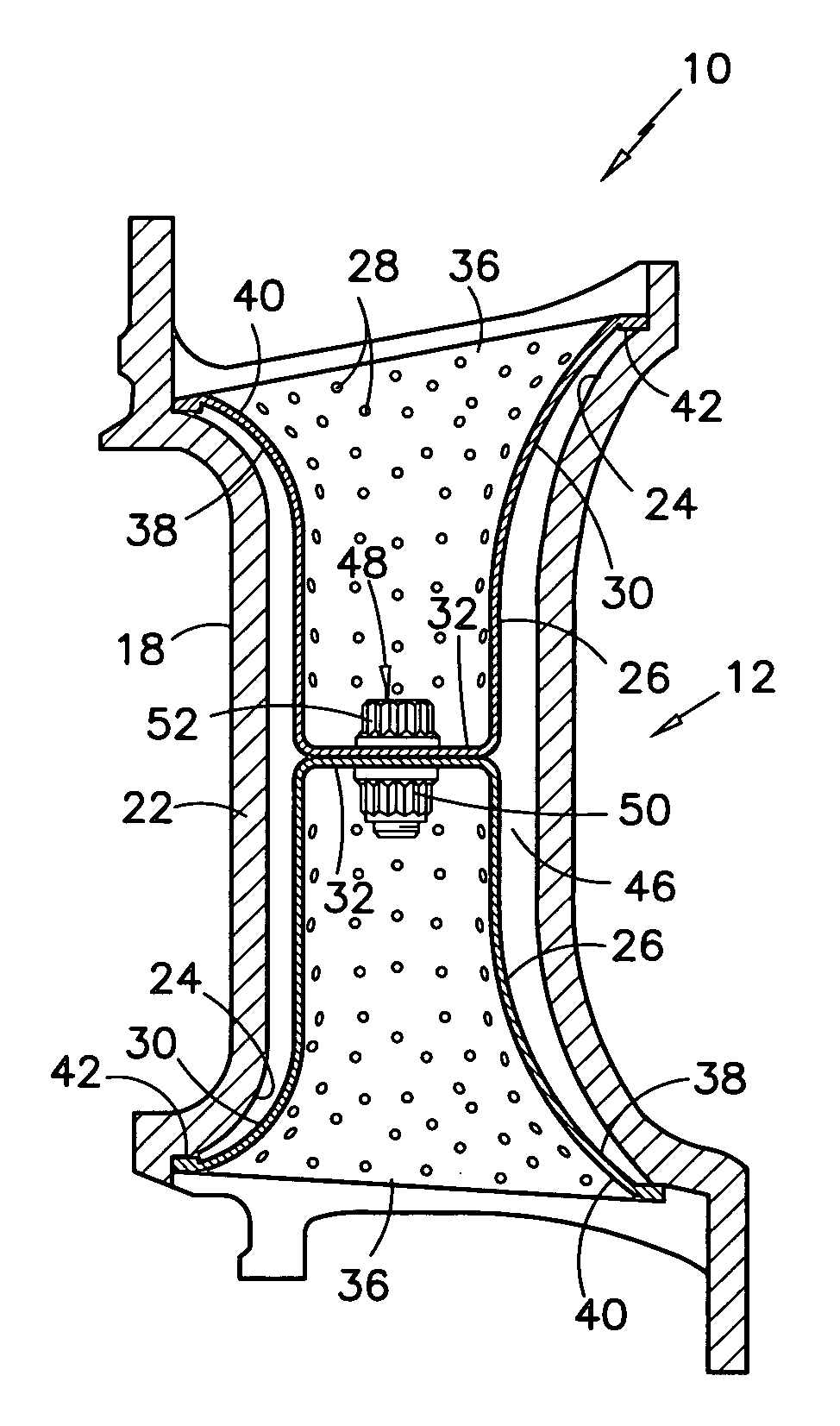
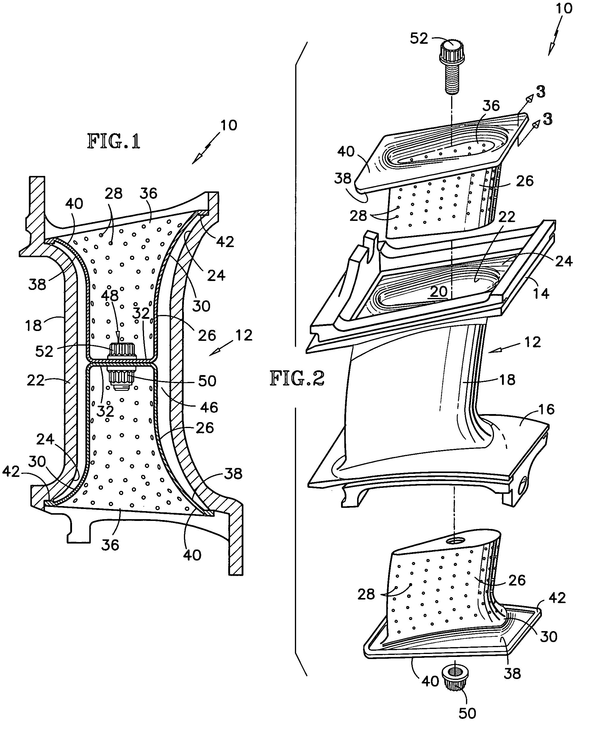
[0019]Referring to FIGS. 1–3 a vane assembly 10 for a turbine engine includes a vane 12 having a first or radially outer platform 14 and a second or radially inner platform 16. The identification of the platforms as radially outer and inner platforms reflects the orientation of the vane when installed in a turbine module of a gas turbine engine. An airfoil 18 extends spanwisely between the platforms. An airfoil shaped internal cavity 20 bounded by vane wall 22 extends spanwisely through the airfoil. The cavity has flared portions 24 at its spanwise extremities as seen best in FIG. 1. The vane is made of a refractory material such as a refractory metal alloy, a ceramic, or a composition comprising intermetallic compounds.

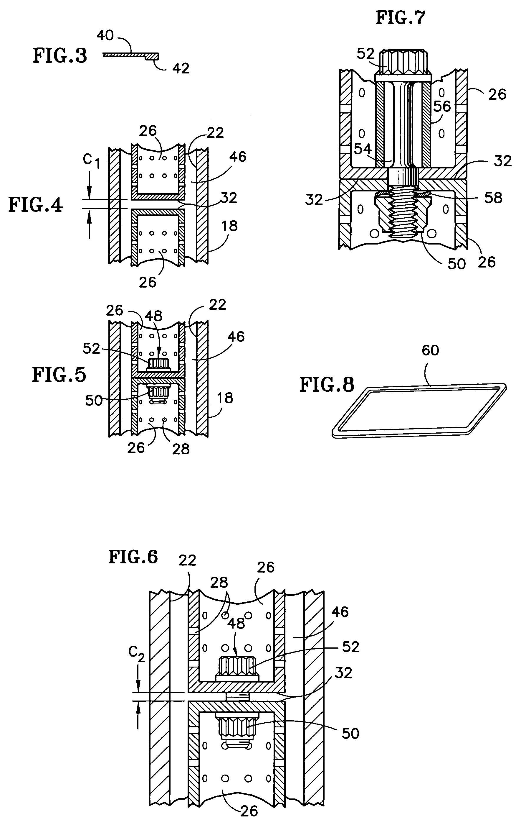
[0020]A metal baffle assembly includes first and second (radially outer and inner) baffles 26 each made of a nickel base alloy. Numerous impingement holes 28 perforate the baffles. Each baffle is airfoil shaped along most of its spanwise length and also has a flared ...


PUM


Abstract

A vane assembly 10 suitable for a turbine engine features a refractory vane 12 with an internal cavity 20 and a pair of flexible metallic baffles 26 extending into the cavity from spanwisely opposite ends of the vane. A rigid fastener 48, such as a nut and bolt assembly applies a tensile load to the baffles. The tensile load is reacted out as a compressive load applied to the vane. In another embodiment, the baffle is relatively rigid but the fastener is flexible. The compressive loading exerted on the vane counteracts the brittleness customarily exhibited by refractory materials and imparts damage tolerance to the vane. The arrangement also allows the use of a metal baffle that can be easily secured to the vane and dispenses with any need for a potentially troublesome seal between the baffles and the spanwise extremities of the vane.

Description

STATEMENT OF GOVERNMENT INTEREST[0001]This invention was made under U.S. Government Contract F-33615-97-C-2779. The Government has certain rights in the invention.TECHNICAL FIELD[0002]This invention relates to a vane assembly of the type useful in gas turbine engines, and particularly to a vane assembly including a tensioned baffle assembly that applies a compressive load to the vane.BACKGROUND OF THE INVENTION[0003]Fluid directing vanes, such as those used in the turbine modules of gas turbine engines, are exposed to hot, gaseous combustion products. Various measures are taken to protect the vanes from the damaging effects of the hot gases. These include making the vane of temperature tolerant nickel or cobalt alloys, applying thermal barrier coatings to the vanes, and cooling the vanes with relatively cool, pressurized air extracted from the engine compressor.[0004]Conventional cooling techniques include impingement cooling. An impingement cooled vane has an internal cavity and a ...

Claims


Application Information

Patent Timeline
Patent Type & Authority Patents(United States)
IPC IPC(8): F01D5/18
CPCF01D5/189F01D9/041F05D2240/10F05D2260/201F05D2230/642F02C7/00F02C3/00F02C7/12
Inventor HARDING, BENJAMIN R.HUDSON, ERIC A.
Owner RTX CORP
Why Eureka
Try Eureka