Impact resistant and damage tolerant aircraft fuselage

a fuselage and impact resistance technology, applied in the field of fuselage section, can solve the problems of increased torsional load, affecting the safety of the aircraft, and releasing debris and impacting the fuselage,

Active Publication Date: 2013-04-25
AIRBUS OPERATIONS SL +1
View PDF16 Cites 26 Cited by
  • Summary
  • Abstract
  • Description
  • Claims
  • Application Information

AI Technical Summary

Benefits of technology

[0029]In embodiments of the fuselage section with an inner reticular structure across the inside of the fuselage, said supporting structure may be configured for providing a full planar supporting surface or a planar polygonal supporting surface or a curved supporting surface to said inner reticular structure. Three different configuration of the inner reticular structure supporting surface are therefore provided for facilitating its incorporation to a particular fuselage section subjected to the impact of a body of given characteristics.
[0030]In embodiments of the fuselage section according to this invention, the inner reticular structure may be formed by panels of a composite or a metallic material including two resistant elements in two different directions to the directions of the traces of the members of the supporting structure that are attached to it by suitable attaching means or discrete elements such as rods, cables or belts of suitable materials oriented in one or two different directions to the directions of the traces of the members of the supporting structure. Four different embodiments of the inner reticular structure are therefore provided for facilitating the implementation of the inner reticular structure for a particular fuselage section affected by an external impact of a body of given characteristics.

Problems solved by technology

One of the problems raised by engines with rotating external blades when installed on the aircraft is related to failure events such as a Blade Release event (i.e. an event where a external blade of one of the engines comes off and hits the fuselage), an Uncontained Engine Rotor Failure event (i.e. an event where a part of the internal rotors of the engine brakes, it is released and hits the fuselage that can also occur on the conventional turbofan engines were the fan blades are not external but ducted inside a fan cowl) or an event where other high energy engine debris is released and hits the fuselage.
These events can generate large damages where considerable zones of the fuselage structure are removed and could lead to a hazardous situation for the safety of the aircraft.
When there is a failure of the engine high energy debris can be released and impact the fuselage.
This increase of torsional load becomes particularly critical when the damages occur on the rear fuselage structure as is the case when the engines are installed on the rear of the aircraft.
In the case that engines are installed on the wing, the damages can occur on the central fuselage in front of the wing.
In this area of the fuselage, the situation can be also dangerous although not as critical as when they are installed in rear part because there are not any torsion load increase coming from the empennage.
A similar situation arises when the aircraft is submitted to damages caused by impacts of other high energy discrete sources such as a released ice formed on the engine blades or a released fragment of the aircraft as for example a trap or a tire debris.
These events can generate also “large damages” on specific fuselage sections, where a considerable area of the fuselage structure can be removed and could lead also to a hazardous situation for the safety of the aircraft.
The disadvantage of the composite materials compared to conventional light weight metallic materials like the aluminum, is its lower impact resistance and damage tolerance capabilities.
No plasticity behavior as on metallic materials is present in composite material and they are not able to absorb high strain energy amounts when deforming.

Method used


Image

  • Impact resistant and damage tolerant aircraft fuselage
  • Impact resistant and damage tolerant aircraft fuselage
  • Impact resistant and damage tolerant aircraft fuselage

Examples


Embodiment Construction

[0055]Although the present invention refers to any fuselage section affected by any impact of a body capable of producing a significant fuselage damage, the following detailed description of the invention will be referred to a rear fuselage section affected by the impact of a body such as a detached blade or other debris released from a propulsion system located in the rear fuselage.

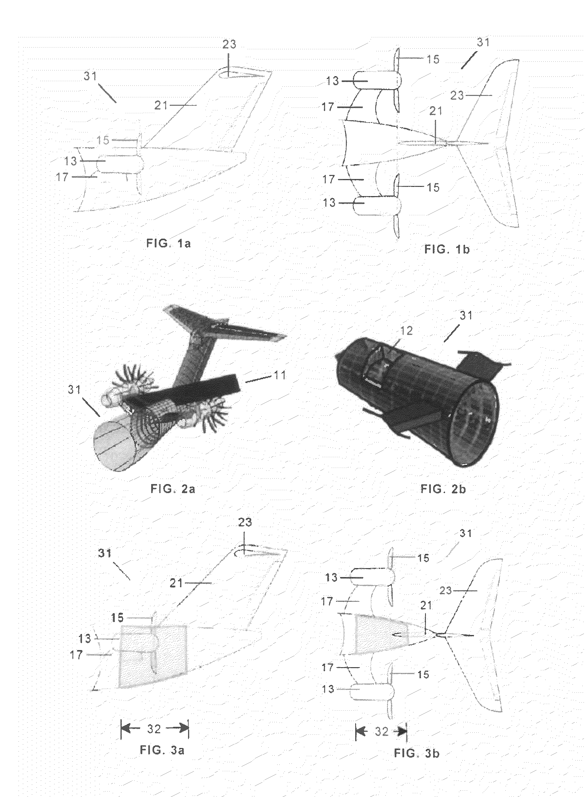
[0056]In an aircraft having a propulsion system 13 with external blades 15 attached to the rear fuselage 31 by means of upstream pylons 17 there is a risk of undergoing a severe damage in, for instance, an event where a blade 15 is detached and impacts the rear fuselage 31 with high energy. In the aircraft shown in FIGS. 1a and 1b the empennage comprises a vertical tail plane 21 and an upper horizontal tail plane 23 behind the propulsion system 13.

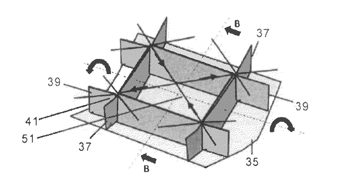
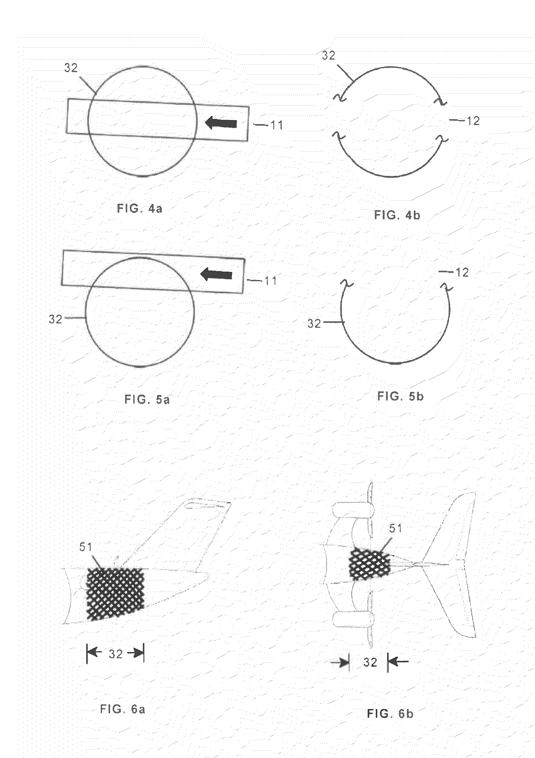
[0057]As shown in FIGS. 2a and 2b a released blade can follow a trajectory 11 impacting on the rear fuselage 31 and producing a large damage 12.

[0058]FIGS. 3a ...


PUM


Abstract

Aircraft fuselage section (32) subjected to impacts of external bodies, the aircraft fuselage having a curved shape with at least a vertical symmetry plane (A-A) and a central longitudinal axis and comprising a skin (35) and a plurality of frames (37) arranged perpendicularly to said longitudinal axis (33), the aircraft fuselage section also comprising at least an inner reticular structure (51, 53) mounted on a supporting structure (41, 43) comprising longitudinal beams (39) attached to the skin (35) and interconnected with said frames (37), said inner reticular structure (51, 53) being arranged for creating at least one closed cell (75) with the skin (35) for improving its resistance and its damage tolerance to said impacts. Said inner reticular structure (51, 53) can be formed by panels (61), rods (65, 65′), cables (67, 67′) or belts (69, 69′).

Description

FIELD OF THE INVENTION[0001]The present invention relates to a fuselage section resistant to impacts of external bodies and tolerant to the damages caused by them and more particularly to a fuselage section of an aircraft powered by engines with rotating blades where the blades or other engine debris can be released and damage said fuselage section.BACKGROUND OF THE INVENTION[0002]There are known commercial and military aircrafts (ATR, C295, A400M etc. . . . ) powered with engine that contains external rotating blades, called propellers, located on the wing. In other cases (CBA vector 123, SARA, AVANTI) such engines are located on the rear part of the aircraft.[0003]One of the problems raised by engines with rotating external blades when installed on the aircraft is related to failure events such as a Blade Release event (i.e. an event where a external blade of one of the engines comes off and hits the fuselage), an Uncontained Engine Rotor Failure event (i.e. an event where a part ...

Claims


Application Information

Patent Timeline
Patent Type & Authority Applications(United States)
IPC IPC(8): B64C1/00
CPCB64C1/06B64C1/061B64C1/062Y02T50/66B64D27/14B64D2027/005B64C1/068Y02T50/60B64C1/0685
Inventor MARTINO GONZALEZ, ESTEBANSANTOLALLA, EDUARDO VINUECORTES, DIEGO FOLCHABAURREA, PABLO GOYAGUINALDO FERNANDEZ, ENRIQUEGUILLEMAUT, JULIEN
Owner AIRBUS OPERATIONS SL
Why Eureka
Try Eureka