Screw compressor

a screw compressor and compressor technology, applied in the direction of machines/engines, rotary/oscillating piston pump components, liquid fuel engines, etc., can solve the problems of oil-related maintenance work, oil management, unnecessary, etc., and achieve the effect of achieving a smooth thermal expansion of the screw rotor

Active Publication Date: 2006-09-12
KOBELCO COMPRESSORS CORP
View PDF15 Cites 18 Cited by
  • Summary
  • Abstract
  • Description
  • Claims
  • Application Information

AI Technical Summary

Benefits of technology

[0016]For the purpose of eliminating the above-mentioned conventional problems, the present invention intends to provide a screw compressor which permits structural simplification, reduction of size, and lightening of a maintenance burden.
[0019]Therefore, in this screw compressor, a condensed refrigerant can be fed into a liquid state to bearing portions and can be utilized for lubrication and sealing, thus eliminating the need of using oil. As a result, all of oil-related devices, including oil separating / recovering unit, and oil pipes, that have so far occupied a fairly large proportion in such points as structural complication, increase of the entire machine volume and installation area, and increase of cost, become unnecessary and the entire machine structure is simplified and is reduced in size. In addition, oil-related maintenance works and the management of oil, which have so far been a burden in the use of oil, become unnecessary. Thus, various effects are obtained.
[0021]With this construction, in addition to the above effects, there is attained an effect that it is possible to cope with a thermal expansion of screw rotors more smoothly.

Problems solved by technology

In addition, oil-related maintenance works and the management of oil, which have so far been a burden in the use of oil, become unnecessary.

Method used


Image

  • Screw compressor
  • Screw compressor
  • Screw compressor

Examples


Embodiment Construction

[0026]An embodiment of the present invention will be described below with reference to the drawings.

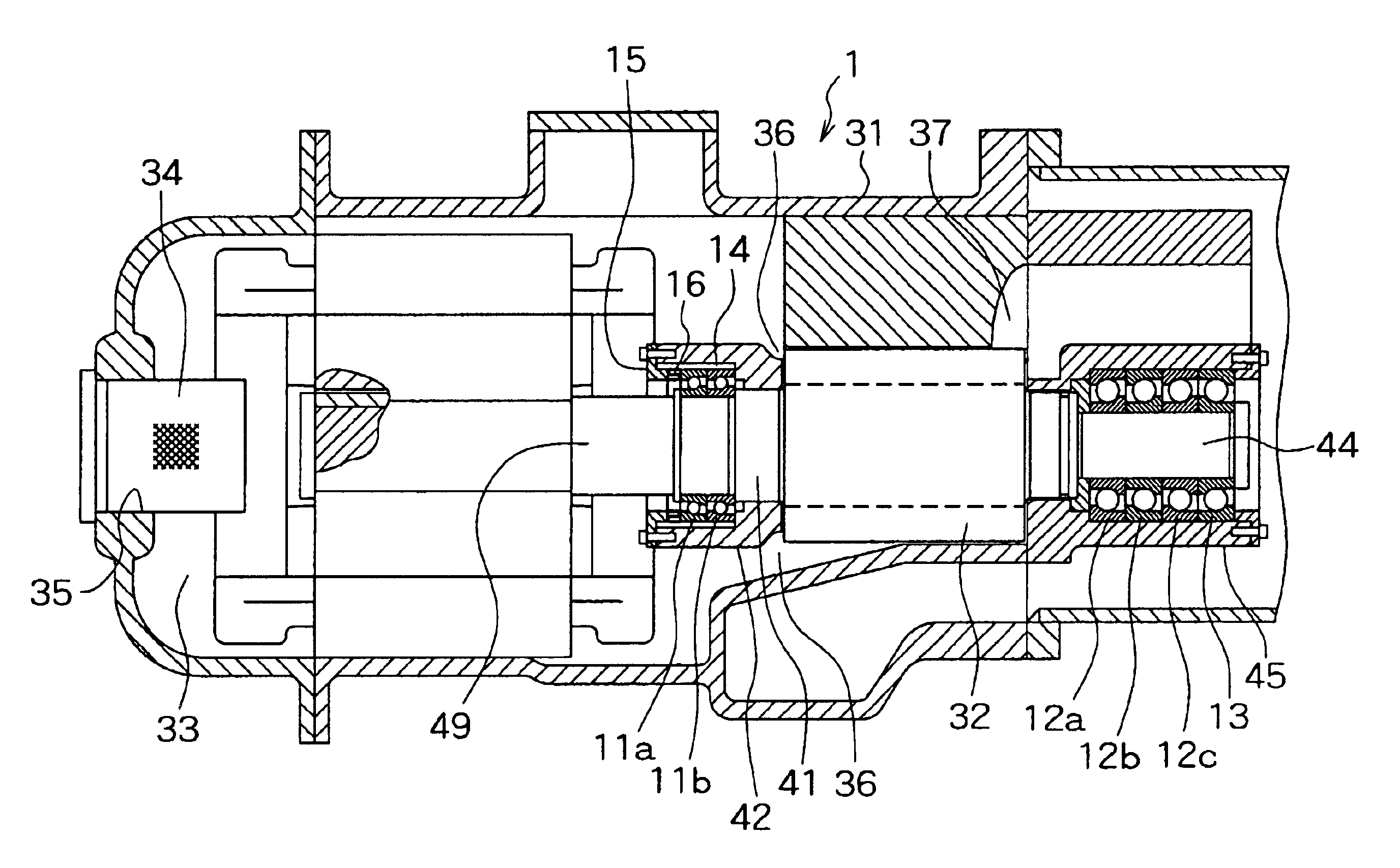
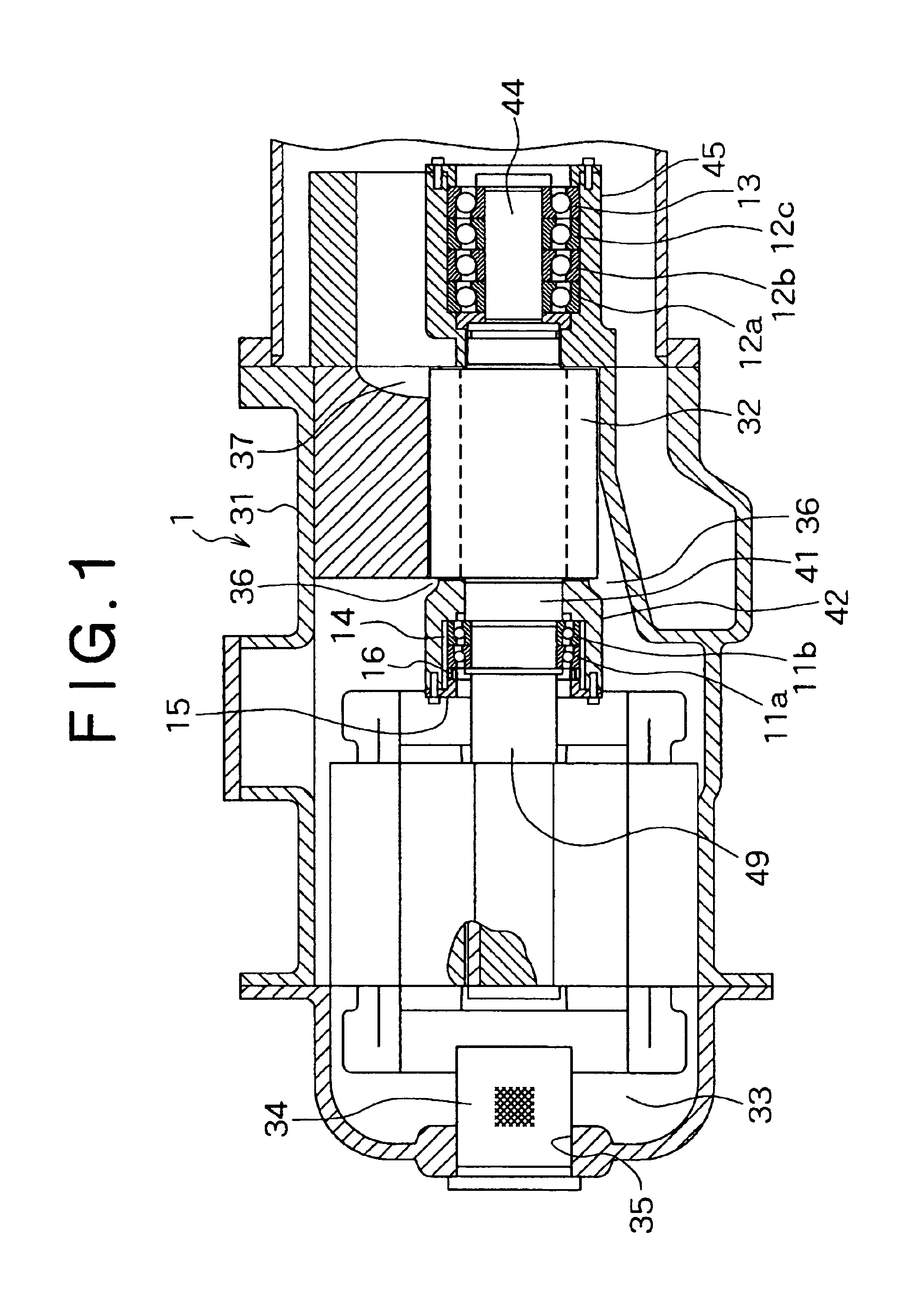
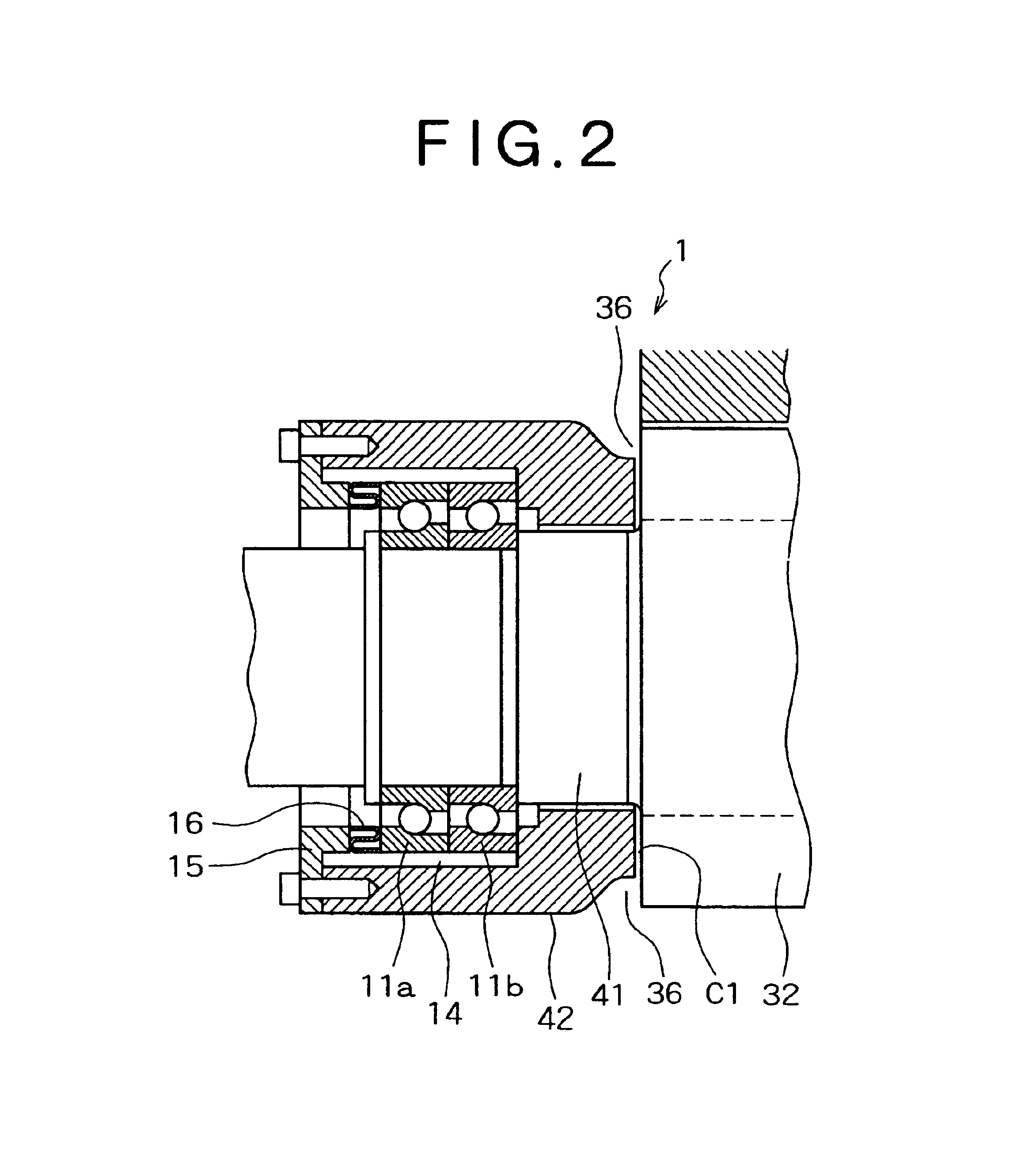
[0027]FIGS. 1 to 3 illustrate a screw compressor 1 for a refrigerator according to the present invention.

[0028]The screw compressor 1 has a pair of intermeshing male and female screw rotors 32 and a motor 33 within an integral type casing 31. At one end of the integral type casing 31 is formed a gas inlet 35 which is provided with a filter 34. At an end portion of the screw rotors 32 located close to the motor 33 is formed a suction port 36, while at an opposite end portion thereof is formed a discharge port 37.

[0029]The suction-side rotor shaft 41 of one of the paired male and female screw rotors 32 shown in FIG. 1 is coupled for integral rotation to an output shaft 49 of the motor 33, and the screw rotors 32 are rotated by the motor 33.

[0030]When the screw compressor 1 is applied to a refrigerator, a gaseous refrigerant which has entered the screw compressor 1 from the gas inlet 35 ...


PUM


Abstract

In a screw compressor for a refrigerator, suction-side rotor shafts of screw rotors are supported rotatably by angular ball bearings for forward thrust load, an annular gap is formed between the angular ball bearings and a suction-side bearing casing, and outermost end faces of outer rings of the angular ball bearings are pressed through a spring member by means of a presser member fixed to an end face of the suction-side bearing casing, whereby the angular ball bearings are held movably in the thrust direction within the suction-side bearing casing. Discharge-side rotor shafts of the screw rotors are supported rotatably by angular ball bearings for forward thrust load and an angular ball bearing for reverse thrust load which are held at predetermined certain positions within a discharge-side bearing casing. A screw compressor which permits structural simplification, reduction of size, and lightening of a maintenance burden is provided.

Description

BACKGROUND OF THE INVENTION[0001]1. Field of the Invention[0002]The present invention relates to a screw compressor and more particularly to a screw compressor for compressing a refrigerant in a refrigerator.[0003]2. Description of the Related Art[0004]Heretofore, a screw compressor applicable to a refrigerator has been publicly known (see, for example, U.S. Pat. No. 6,183,227).[0005]Screw compressors are broadly classified into an oil-cooled type screw compressor and an oil-free type screw compressor. In an oil-cooled type screw compressor, oil is fed into a rotor chamber for the purpose of sealing between rotors, sealing between rotors and an inner wall surface of the rotor chamber, cooling a portion whose temperature rises with compression, and lubrication. In an oil-free type screw compressor, oil is not fed into a rotor chamber, a bearing portion is completely shut off from the rotor chamber by sealing, and a synchronous gear is used for the transfer of a rotational drive force...

Claims


Application Information

Patent Timeline
Patent Type & Authority Patents(United States)
IPC IPC(8): F01C1/16F01C21/02F04C18/16F04C23/00F04C29/00F04C29/02
CPCF01C21/02F04C18/16Y10S418/01F04C2240/50F04C23/008
Inventor TSUBOI, NOBORU
Owner KOBELCO COMPRESSORS CORP
Why Eureka
Try Eureka