
Terminal and a method of forming it

a technology of terminals and cylinders, applied in the direction of coupling device details, coupling device connections, coupling contact members, etc., can solve the problems of increasing contact resistance, and achieve the effects of reducing inserting force, low rigidity, and large radius of curvatur

Inactive Publication Date: 2006-09-12
SUMITOMO WIRING SYST LTD
View PDF7 Cites 3 Cited by
  • Summary
  • Abstract
  • Description
  • Claims
  • Application Information

AI Technical Summary

Benefits of technology

This design reduces the peak inserting force and stabilizes the insertion process by allowing the mating terminal to be aligned easily with a low initial force, achieving a stable posture and lower contact resistance.

Problems solved by technology

However, this also causes a problem of an increased contact resistance upon inserting the tab-shaped terminal.

Method used


Image

  • Terminal and a method of forming it
  • Terminal and a method of forming it
  • Terminal and a method of forming it

Examples


Embodiment Construction

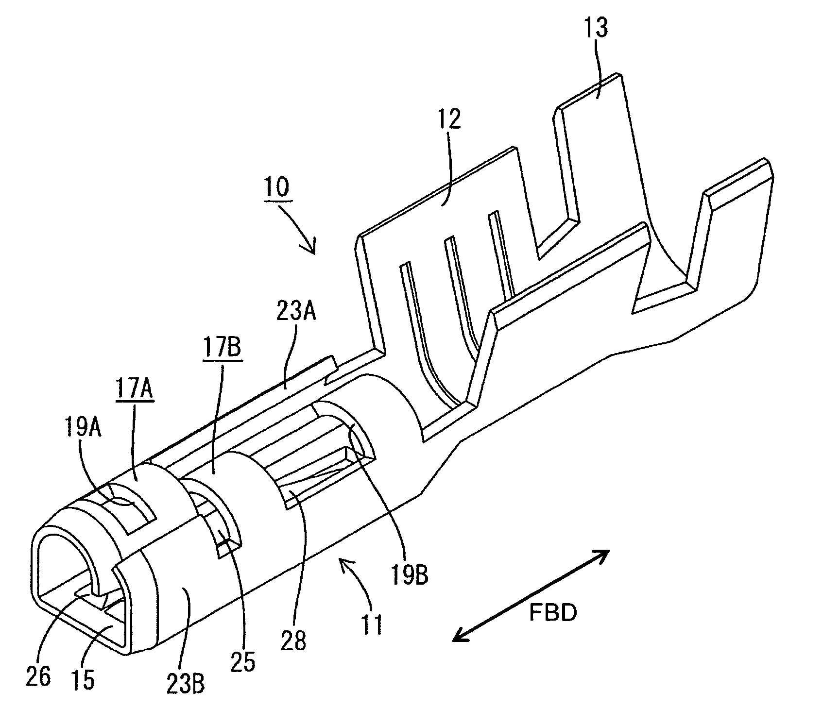
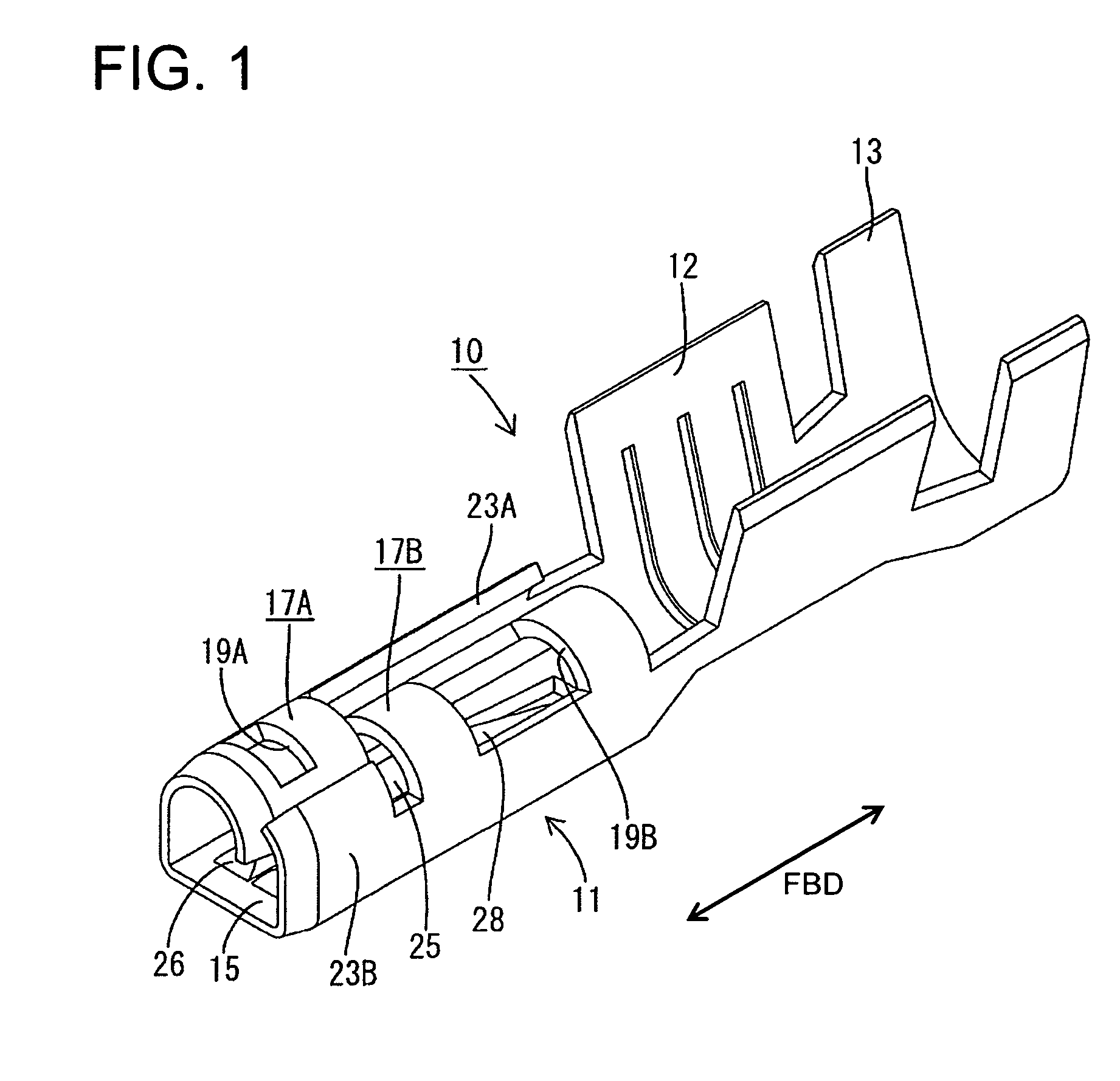
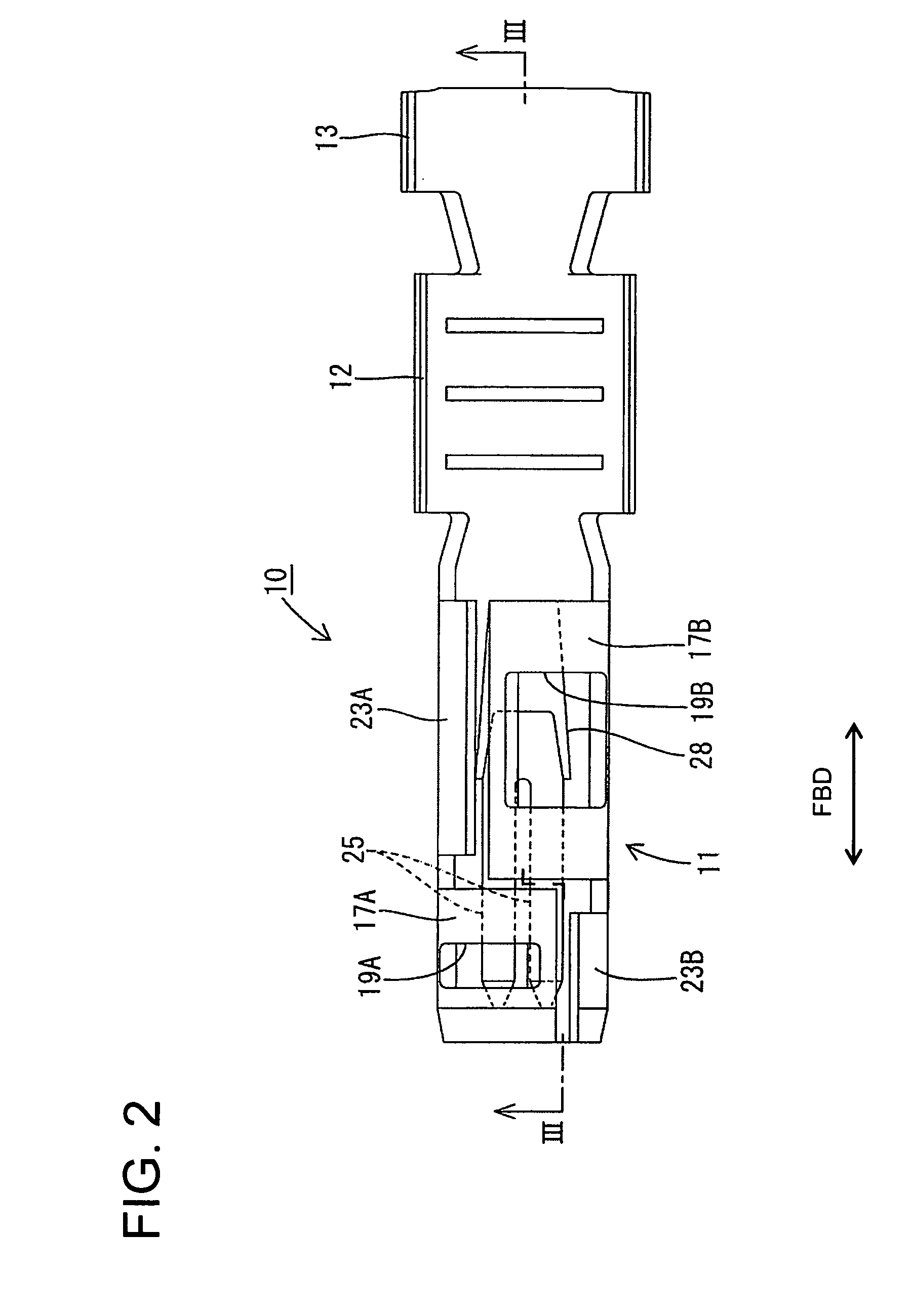
[0029]A terminal according to the invention is identified by the numeral 10 in FIGS. 1 to 5. The terminal 10 is formed by press-working a metal plate having a good electrical conductivity to define a connecting portion 11, a wire barrel 12 behind the connecting portion 11 and an insulation barrel 13 behind the wire barrel 12. The wire barrel 12 is configured for crimped connection with an end of a core W1 of an insulated wire W, while the insulation barrel 13 is configured for crimped connection with an end of an insulation coating W2.

[0030]The connecting portion 11 includes a substantially flat receiving plate 15 that is narrow and long along forward and backward directions FBD. The receiving plate 15 has, for example, a length that is more than about one third, preferably about half the entire length of the terminal 10.

[0031]A front connecting piece 17A is formed near the front end of the receiving plate 15 and at the left side of the receiving plate 15, when viewed from the front...


PUM


Abstract

A terminal (10) has opposite front and rear ends and a receiving plate with lateral edges. Front and rear connecting pieces (17A, 17B) project up from the lateral edges and then curve inwardly. The front connecting piece (17A) is shorter in a front-to-rear direction than the rear connecting piece (17B). The connecting pieces (17A, 17B) extend beyond the widthwise center of the receiving plate (15). Thus, the curved connecting pieces (17A, 17B) overlap when viewed in forward and backward directions. The connecting pieces (17A, 17B) have window holes (19A, 19B) for weakening. The provision of front and rear connecting pieces (17A, 17B) causes inserting force peaks at the front and rear when a mating tab-shaped terminal is inserted. As a result, a peak value is lowered to reduce the inserting force.

Description

BACKGROUND OF THE INVENTION[0001]1. Field of the Invention[0002]The invention relates to a terminal and to a method of forming it.[0003]2. Description of the Related Art[0004]Japanese Unexamined Patent Publication No. H05-290898A discloses a terminal that has a flat receiving plate with two opposite lateral edges that extend along forward and backward directions. Connecting pieces extend up from the opposite lateral edges of the receiving plate and curve in towards one another to define a substantially heart-shaped space. A mating tab-shaped terminal can be inserted into this space and is squeezed resiliently between the receiving plate and leading ends of the connecting pieces to establish an electrical connection. Terminals of this type are used in automotive wiring harnesses and are available from many companies. For example, The Whitaker Co. sells terminals of this general type under the trademark FastOn.[0005]Terminal fittings of the type shown in Japanese Unexamined Patent Pub...

Claims


Application Information

Patent Timeline
Patent Type & Authority Patents(United States)
IPC IPC(8): H01R13/11H01R4/18H01R13/115
CPCH01R13/113H01R4/185
Inventor NIMURA, KAZUHIKO
Owner SUMITOMO WIRING SYST LTD
Learn More