Emergent power supply system and method of achieving input current balance in such system

a technology of power supply system and input current balance, which is applied in the direction of emergency power supply arrangement, dc-ac conversion without reversal, transportation and packaging, etc., can solve the problems of power grid load vulnerability, waste of energy usage, and inability to provide the battery associated with the battery to other ups modules

Active Publication Date: 2006-09-12
DELTA ELECTRONICS INC
View PDF2 Cites 35 Cited by
  • Summary
  • Abstract
  • Description
  • Claims
  • Application Information

AI Technical Summary

Benefits of technology

[0012]A second object of the present invention is to provide a method of achieving input current balance in an emergent power supply system.

Problems solved by technology

At this moment, the load will continue to be supported by the unprotected utility power, leaving the load vulnerable to the power grid.
When the inverter of any one of the UPS modules is malfunctioned, the battery associated therewith is not available to other UPS modules.
That would results in a waste in energy usage and an inefficiency in spatial utilization.
Also the parallel redundant UPS system with common battery operation can increase the MTBF (mean time between failure) of the UPS module significantly.
However, the prior art UPS system suffers from several disadvantages because of the unbalance among the input currents of the internal UPS modules.
However, as described above this configuration has the negative factors of inefficient usage of battery power and costly manufacturing budget on battery.
Because the input impedance of each UPS module is different with one another, the input currents of the UPS modules become unbalanced.
The unbalanced input currents may cause severe problems to the rectifier 12,22, for example, the rectifier 12,22 may be overloaded and the semiconductor components used therein may have a shorter lifetime due to overheating.

Method used


Image

  • Emergent power supply system and method of achieving input current balance in such system
  • Emergent power supply system and method of achieving input current balance in such system
  • Emergent power supply system and method of achieving input current balance in such system

Examples


first embodiment

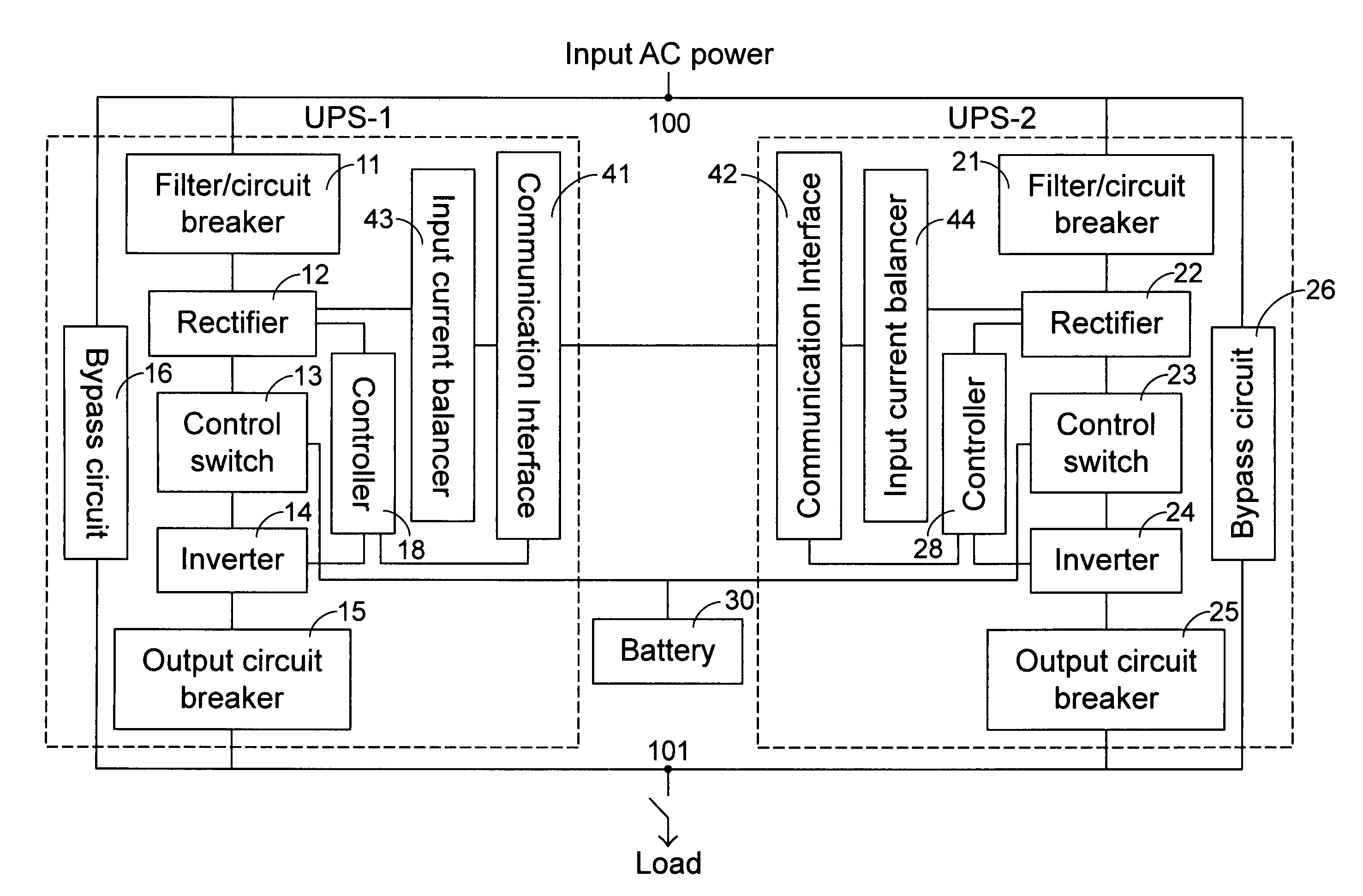
[0025]References are now made to FIG. 5, a possible layout of the system for carrying out the input current balancing method according to the present invention is illustrated. In FIG. 5, the input current balancer 43,44 includes an average input current generator 51 which collects the operation status information from a multiplicity of backup power supply modules, i.e. the input currents of the multiplicity of backup power supply modules, and calculates an average input current IAVG by summing the input currents of the multiplicity of backup power supply module and dividing the sum of the input currents by the number of the multiplicity of backup power supply modules. The calculated average input current IAVG is then compared with an input current IN associated with a backup power supply module thereof by an adder-subtractor 52 coupled to the average input current generator 51 in order to generate a differential input current IDIF. The differential input current IDIF is then amplifi...

second embodiment

[0026]References are now made to FIG. 6, an alternative embodiment illustrating a possible layout of the system for carrying out the input current balancing method according to the present invention is illustrated. The system used to achieve input current balance as shown in FIG. 6 is analogous to that of FIG. 5, however, the system as indicated in FIG. 6 uses an average input power generator 61 which collects the input powers of a multiplicity of backup power supply modules and generates an average input power PAVG by summing the input powers of the multiplicity of backup power supply modules and dividing the sum of the input powers by the number of the multiplicity of backup power supply modules. The average input power PAVG is then compared with an input power PN associated with a backup power supply module thereof by an adder-subtractor 62 coupled to the average input power generator 61 in order to generate a differential input current PDIF. The differential input power current ...


PUM


Abstract

An emergent power supply system capable of automatically balancing the input currents of a multiplicity of backup power supply modules therein is addressed. The emergent power supply system according to the present invention includes a multiplicity of backup power supply modules, wherein each of the multiplicity of backup power supply modules includes an input current balancer capable of collecting an operation status information of the backup power supply modules, generating an average of the operation status information, generating a differential value by comparing the average of the operation status information with an operation status information associated with a backup power supply modules thereof, amplifying the differential value in accordance with a predetermined proportion, and instructing an output voltage stabilizer of a rectifier to generate a rectifying control signal according to an amplified differential value to control the on / off operations of the rectifier within the backup power supply modules.

Description

FIELD OF THE INVENTION[0001]The present invention is related to an emergent power supply system, and more particularly to an emergent power supply system capable of achieving input current balance and an input current balancing method used in such system.BACKGROUND OF THE INVENTION[0002]With the rapid development of information technology and burgeoning expansion in high-tech industry, an uninterruptible power supply (UPS) has been used as an emergent power supply device for a great amount of electronic devices. Most of sophisticated electric instruments and facilities count on high-quality power supply to maintain a normal operation condition. Currently the UPS has become an optimum solution to ensure the best power supply quality in the event of power outage.[0003]Despite the advantages that an UPS can provide, however, when a legacy UPS is put to maintenance or repair, the power conduction passageway of the UPS will be changed by a bypass switch. At this moment, the load will con...

Claims


Application Information

Patent Timeline
Patent Type & Authority Patents(United States)
IPC IPC(8): H02J1/10H02H3/00H02H7/00H02J3/46H02J9/06H02M7/48H02M7/493
CPCH02J3/46H02M7/493H02J9/062
Inventor WANG, SHYNE-JENQLIAO, JEN-CHUAN
Owner DELTA ELECTRONICS INC
Why Eureka
Try Eureka