Sensor for determining the angular position of a radiating point source in two dimensions

a technology of a point source and a sensor, which is applied in the direction of optical radiation measurement, instruments for comonautical navigation, instruments, etc., can solve the problems of not providing immunity from errors and not yielding sufficient resolution, and achieve the effect of accurate determination

Inactive Publication Date: 2006-09-12
ASCENSION TECH
View PDF4 Cites 98 Cited by
  • Summary
  • Abstract
  • Description
  • Claims
  • Application Information

AI Technical Summary

Benefits of technology

[0008](3) Since the transmissivity pattern on the mask varies in two dimensions, relative movements between the point source and the sensor yield variations in two dimensions in such a manner as to yield two correlation signal peaks that indicate an incident angle in two dimensions. From this information, the angular position of the radiating point source with respect to the detector may be accurately determined in two dimensions.

Problems solved by technology

A drawback of such a system is that it does not provide immunity from errors resulting from reflections, and does not yield sufficiently high enough resolution as is the case with techniques employing pseudo-random patterns and correlation techniques.

Method used


Image

  • Sensor for determining the angular position of a radiating point source in two dimensions
  • Sensor for determining the angular position of a radiating point source in two dimensions
  • Sensor for determining the angular position of a radiating point source in two dimensions

Examples


Embodiment Construction

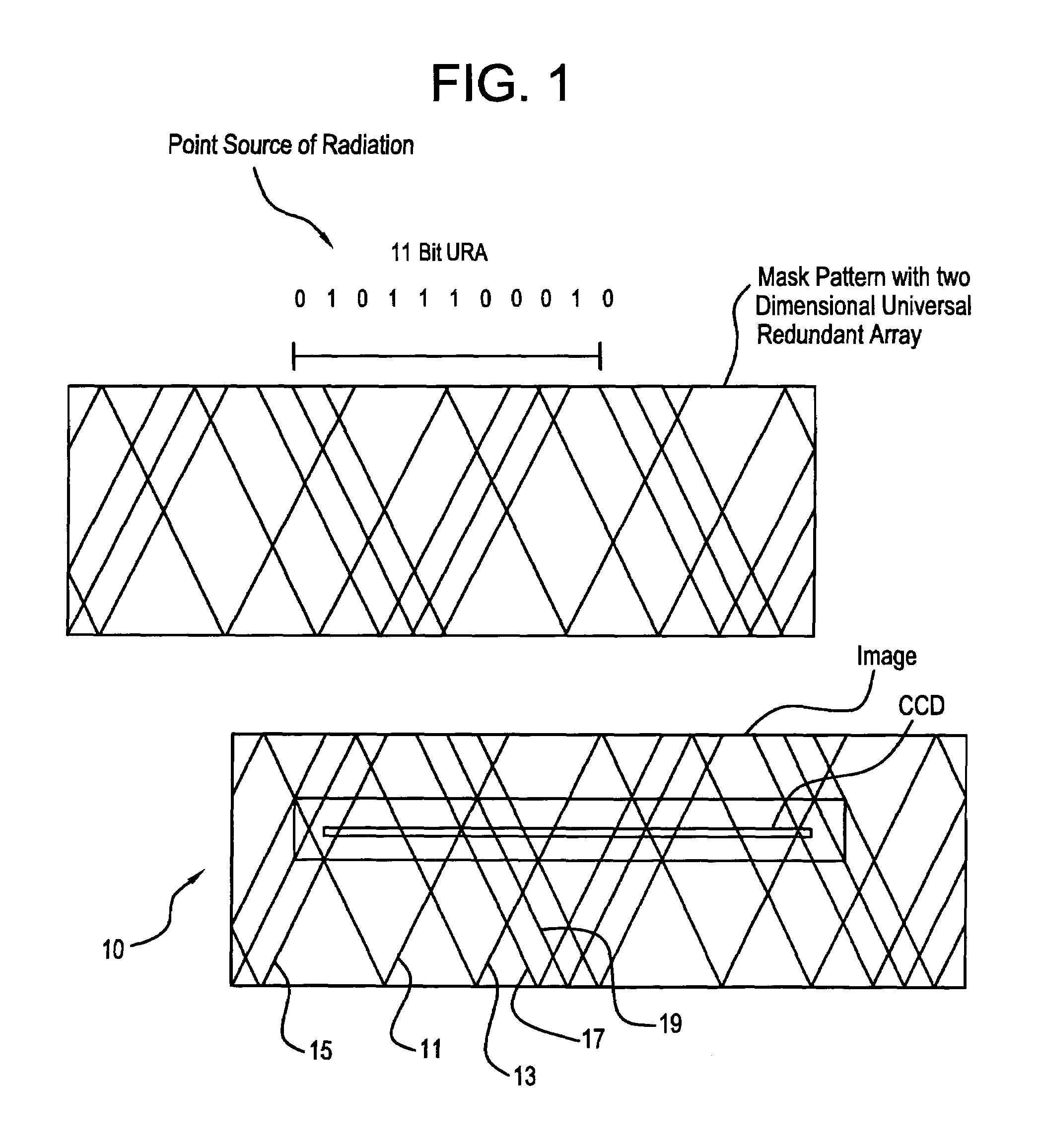
[0028]With reference, first, to FIG. 1, a rectangular mask is generally designated by the reference numeral 10 and is seen to include a pseudo-random pattern of “V” slits 11, 13, 15, 17, 19, etc. For simplicity of description, not every “V” slit is provided with a reference numeral, however, viewing of FIG. 1 provides a full explanation of the pattern which is being described herein.

[0029]As should be understood by those of ordinary skill in the art, where each “V” slit provides 50% transmissivity, locations where adjacent “V” slits overlap form locations of 100% transmissivity. As another example, where non-overlapping portions of the pattern have 50% transmissivity and overlapping portions of the pattern have 0% transmissivity, the mask background consequently comprises a region with 100% transmissivity.

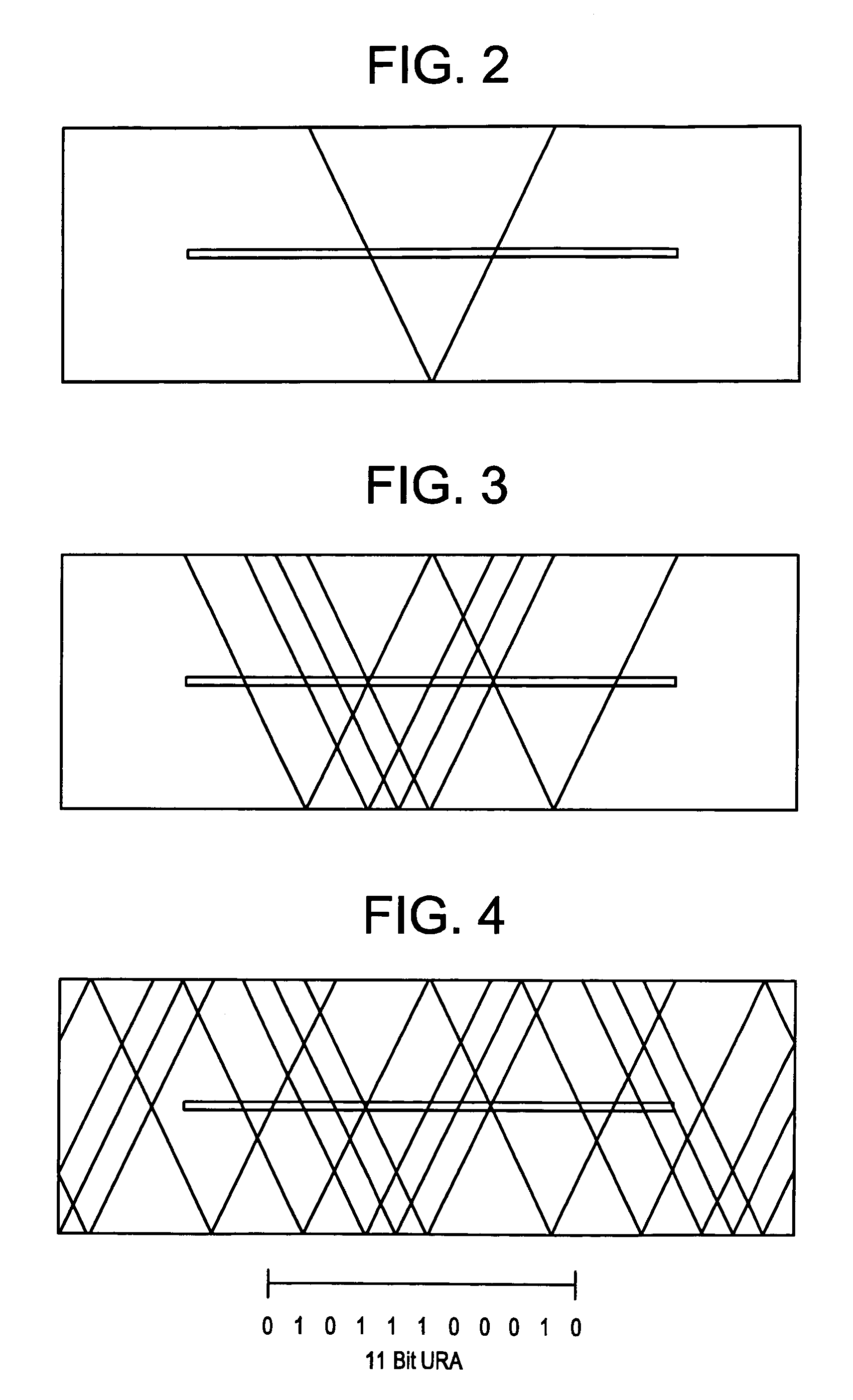
[0030]FIGS. 2–4 show a variety of “V” slit patterns, with FIG. 2 showing a single “V” slit and FIGS. 3 and 4 showing more complex combinations of “V” slits. As should be understood...


PUM


Abstract

Embodiments of a device and a technique are disclosed for locating the angular position of a radiating point source with respect to a detector comprising a point source of radiation, a variable transmissivity mask with pseudo-random variations, a multi-element detector and computing means for interpreting the detected image. The mask pattern, when illuminated by a point source of radiation, casts an image on the detector array. Computing means determine the pattern shift to allow determination of point source angular location in two dimensions. The mask transmissivity pattern and corresponding image vary in two dimensions, in such a manner as to yield two correlation peaks that indicate the incident angle in two dimensions. The differential shift and common mode shift in correlation peaks indicate the respective angles of incidence, allowing determination of the angular position of the light source.

Description

BACKGROUND OF THE INVENTION[0001]The present invention relates to a sensor for determining the angular position of a radiating point source in two dimensions. The present invention has particular pertinence in the field of surgery, with particular reference to close range surgical instrument tracking. Additionally, the present invention is applicable in the fields of virtual reality and pilot head tracking systems.[0002]In the prior art, systems have been devised that employ one dimensional masked or coded apertures placed above multi-element one dimensional detectors. Such structure is disclosed in U.S. Pat. Nos. 4,810,870 and 5,408,323. In such systems, correlation techniques are employed to determine the position of a projected pseudo-random pattern on a detector surface by comparing signals from fixed detector elements arranged in a unique pattern or from comparison with fixed reference signals previously stored in a computer.[0003]Additionally, it is known in the prior art to u...

Claims


Application Information

Patent Timeline
Patent Type & Authority Patents(United States)
IPC IPC(8): G01B11/26G01C1/00G01D5/26G01D5/32
CPCG01B11/26G01D5/32G01D5/26G01C1/00
Inventor ODELL, DON
Owner ASCENSION TECH
Why Eureka
Try Eureka