Power electronic system with passive cooling

a technology of electronic systems and passive cooling, applied in the direction of cooling/ventilation/heating modifications, circuit arrangements on insulating boards, semiconductor/solid-state device details, etc., can solve problems such as device failure, achieve reliable performance of very high-current and power-dissipating electronics, and eliminate cost, complexity and space requirements.

Active Publication Date: 2006-09-12
DELPHI TECH IP LTD
View PDF23 Cites 18 Cited by
  • Summary
  • Abstract
  • Description
  • Claims
  • Application Information

AI Technical Summary

Benefits of technology

[0009]High-power electronic devices associated with high-current printed circuit boards generate heat during normal and transient operation that may cause overheating and device failure if the thermal energy is not sufficiently conducted away from the electronic device. The combination of utilizing passive heat pipes with thermal transient suppression material to dissipate heat from electronic devices on high-current printed circuit boards provides an efficient, low-cost, and compact design. Applications such as in the automotive environment, for example, energy conversion or motor control power devices, require low-cost, compact and reliable heat dissipation such as that provided by the present inventive assembly.
[0010]Advantageously, the thermal transient suppression material provides excellent transfer of transient thermal energy away from the electronic device while the heat pipe provides efficient transfer of steady state thermal energy from the electronic device and transfer of thermal energy from the thermal transient suppression material over a period of time so that the material may again return to a solid state and provide renewed transient thermal energy absorption.
[0019]Advantageously, the present invention provides high-performance cooling for proper operation and reliable performance of very high-current and power-dissipating electronics. Additionally, the present invention may utilize only passive heat dissipation materials and assemblies, thereby eliminating the cost, complexity and space requirement of external mechanical pumps, fluid radiators, and the associated fluid containment and routing plumbing.

Problems solved by technology

High-power electronic devices associated with high-current printed circuit boards generate heat during normal and transient operation that may cause overheating and device failure if the thermal energy is not sufficiently conducted away from the electronic device.

Method used


Image

  • Power electronic system with passive cooling
  • Power electronic system with passive cooling
  • Power electronic system with passive cooling

Examples


Embodiment Construction

[0025]The embodiments disclosed below are not intended to be exhaustive or limit the invention to the precise forms disclosed in the following detailed description. Rather, the embodiments are chosen and described so that others skilled in the art may utilize their teachings.

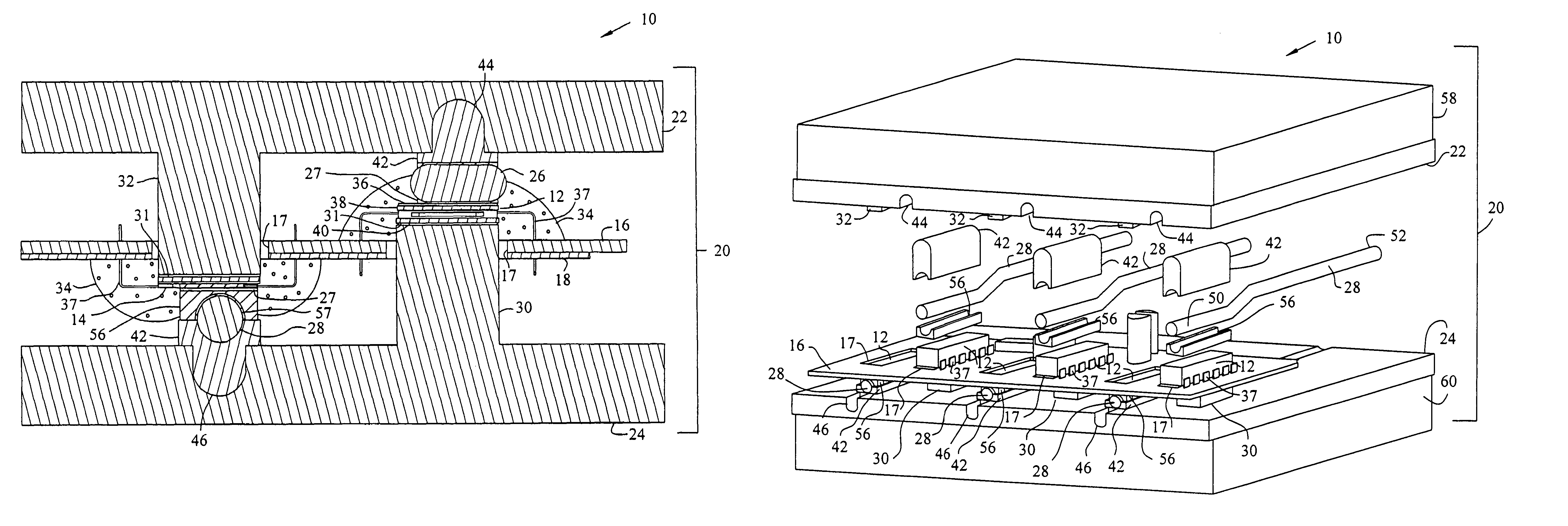
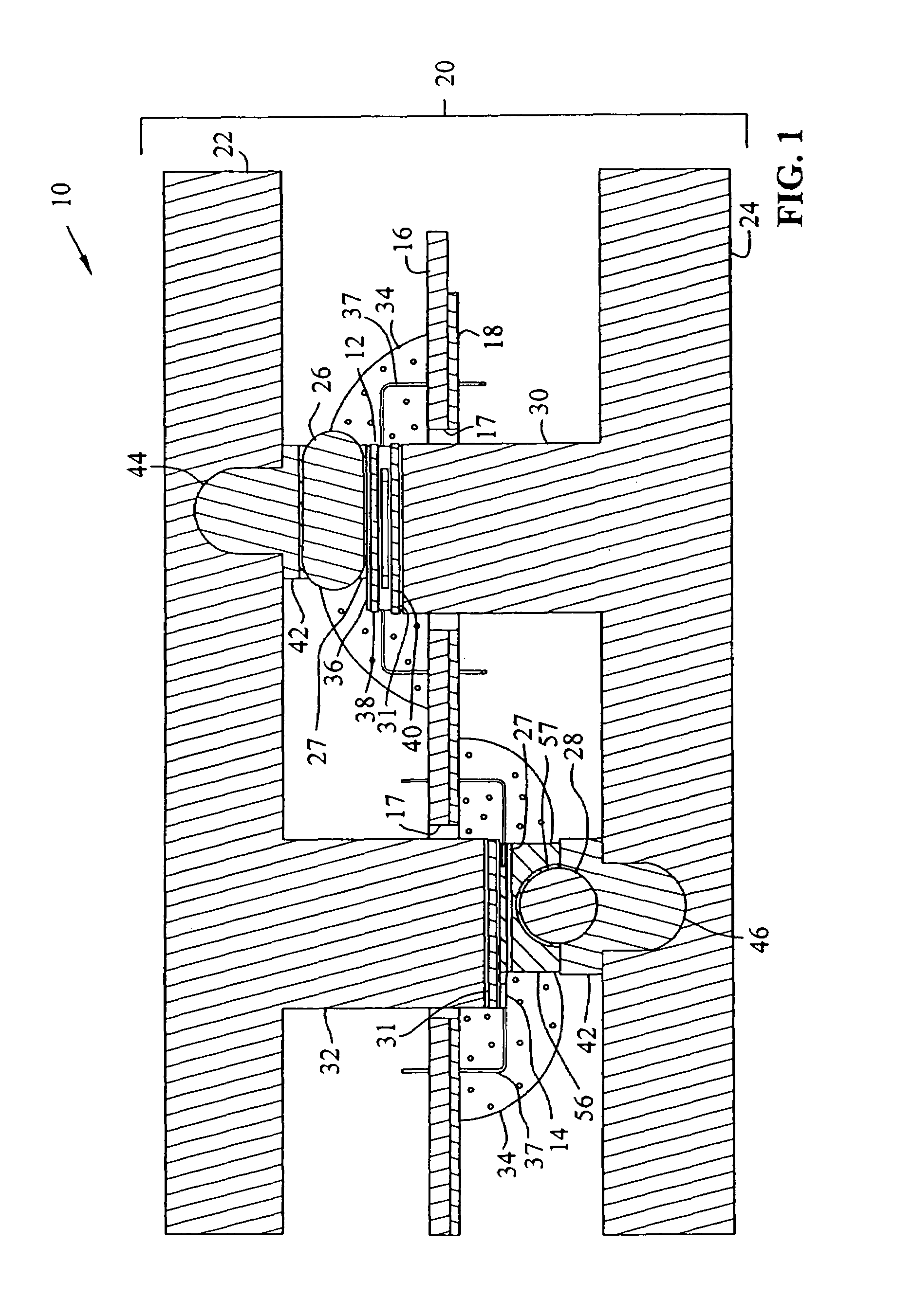
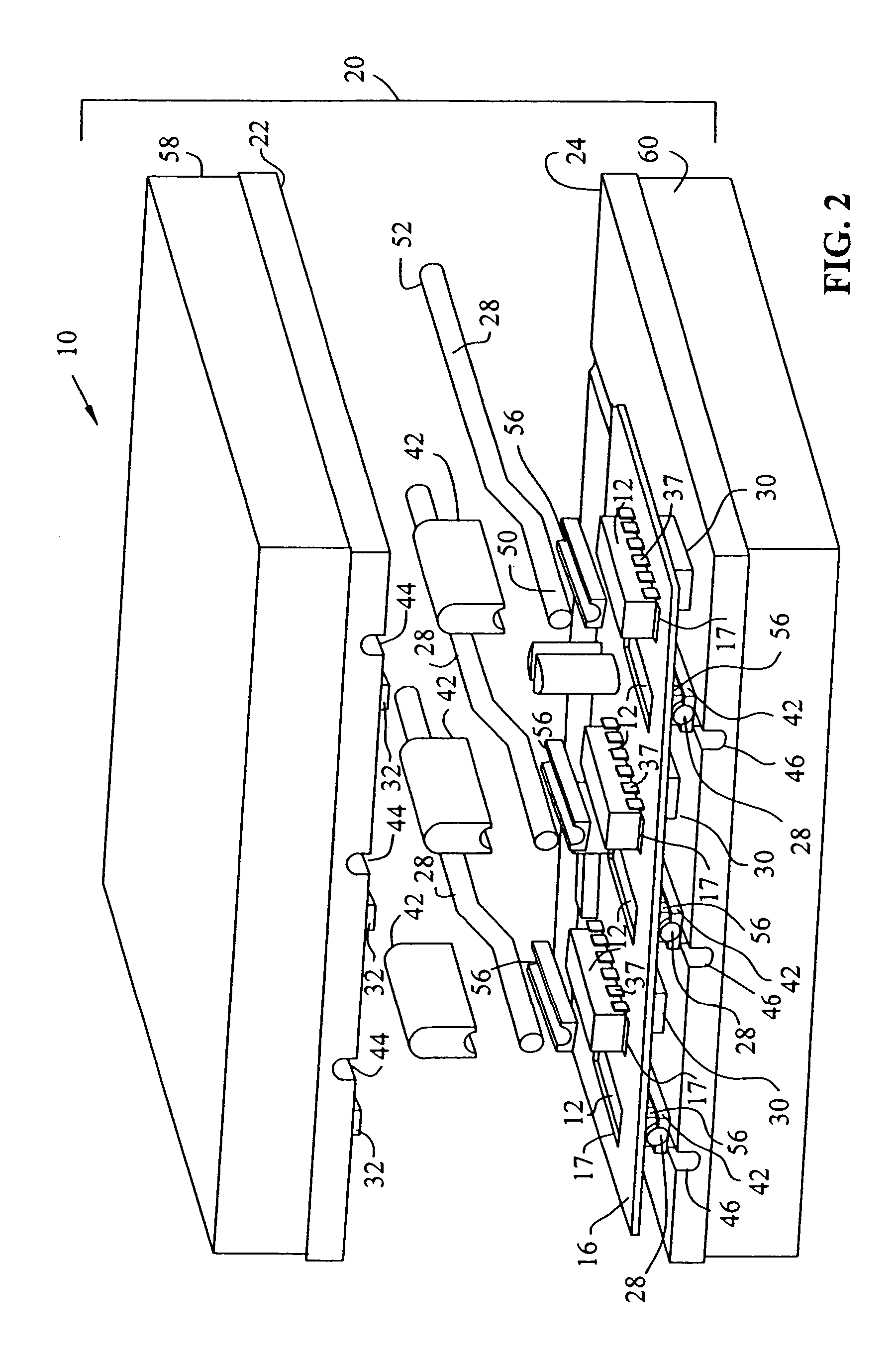
[0026]FIGS. 1 and 2 show first exemplary electronic assembly 10 which provides heat dissipation for first electronic device 12 and second electronic device 14. Electronic devices 12 and 14 are supported by opposite sides of substrate 16 which may include high-current conductors 18. Electronic devices 12 and 14 and substrate 16 may be enshrouded by case 20. Case 20 may include first case portion 22 and second case portion 24. Heat dissipation features of first electronic assembly 10 include first heat pipe 26 having an oval cross-section, second heat pipe 28 having a circular cross-section, first pedestal 30, second pedestal 32, thermal coupling members 56, and transient thermal suppression material 34. Pedestals...


PUM


Abstract

The present invention relates to an apparatus and method for dissipating heat from high-power electronic devices. The assembly includes a high-current substrate, such as a printed circuit board supporting an electronic device, a heat pipe thermally coupled with the electronic device and an assembly case which also forms a heat sink, and thermal transient suppression material which may be thermally coupled with the electronic device and the heat pipe.

Description

TECHNICAL BACKGROUND[0001]The present invention generally relates to an assembly and method for dissipating heat generated by electronic devices. More particularly, this invention relates to structures and methods for absorbing and dissipating heat generated by electronic devices.BACKGROUND OF THE INVENTION[0002]Heat generated by electronic devices during normal operation can cause overheating and device failure if not conducted away from the device. Additionally, transient increased heat generated by electronic devices must also be dissipated, although most electronic devices may handle short durations of increased temperature so that the transient thermal energy can be dissipated over an interval of time. Examples of heat dissipation structures and materials include heat sinks, potting compounds, interface materials and heat pipes.[0003]Heat sinks provide good thermal energy conduction away from electronic devices by providing sufficient thermal conductivity and specific heat. Hea...

Claims


Application Information

Patent Timeline
Patent Type & Authority Patents(United States)
IPC IPC(8): H05K7/20H01L23/427H05K7/06
CPCH01L23/427H01L23/4275H01L2924/0002H01L2924/00
Inventor OBERLIN, GARY E.MYERS, BRUCE A.DEGENKOLB, THOMAS A.PEUGH, DARREL E.
Owner DELPHI TECH IP LTD
Why Eureka
Try Eureka